
Brushless motor drive control circuit and brushless motor device using the same

Active Publication Date: 2007-08-02
ROHM CO LTD
View PDF5 Cites 10 Cited by
  • Summary
  • Abstract
  • Description
  • Claims
  • Application Information

AI Technical Summary

Benefits of technology

[0011] Since the brushless motor drive control circuit and the brushless motor device using the same according to the present invention includes the counter electromotive voltage filter circuit for switching at least between first and second time constants according to a rotation speed of the rotor to pass a low-range frequency component corresponding to the time constant, at low-speed rotation, an S / N ratio of a predetermined counter electromotive voltage can be assured by increasing the time constant to enhance noise removal effects and at high-speed rotation, lowering of efficiency of the brushless motor can be suppressed by reducing a delay of a counter electromotive voltage caused by the counter electromotive voltage filter circuit.

Problems solved by technology

More specifically, the noise is switching noise generated when the brushless motor is PWM-driven (pulse width modulation) or the like.

Method used


Image

  • Brushless motor drive control circuit and brushless motor device using the same
  • Brushless motor drive control circuit and brushless motor device using the same
  • Brushless motor drive control circuit and brushless motor device using the same

Examples


Embodiment Construction

[0017] Embodiments of the present invention will be hereafter described with reference to the drawings. In the drawings, like or the same parts are indicated by the same reference characters and accordingly, description thereof is not repeated here.

[0018] In the following, description will be made of a brushless motor drive control circuit and a brushless motor device using the same as a best mode for carrying out the present invention.

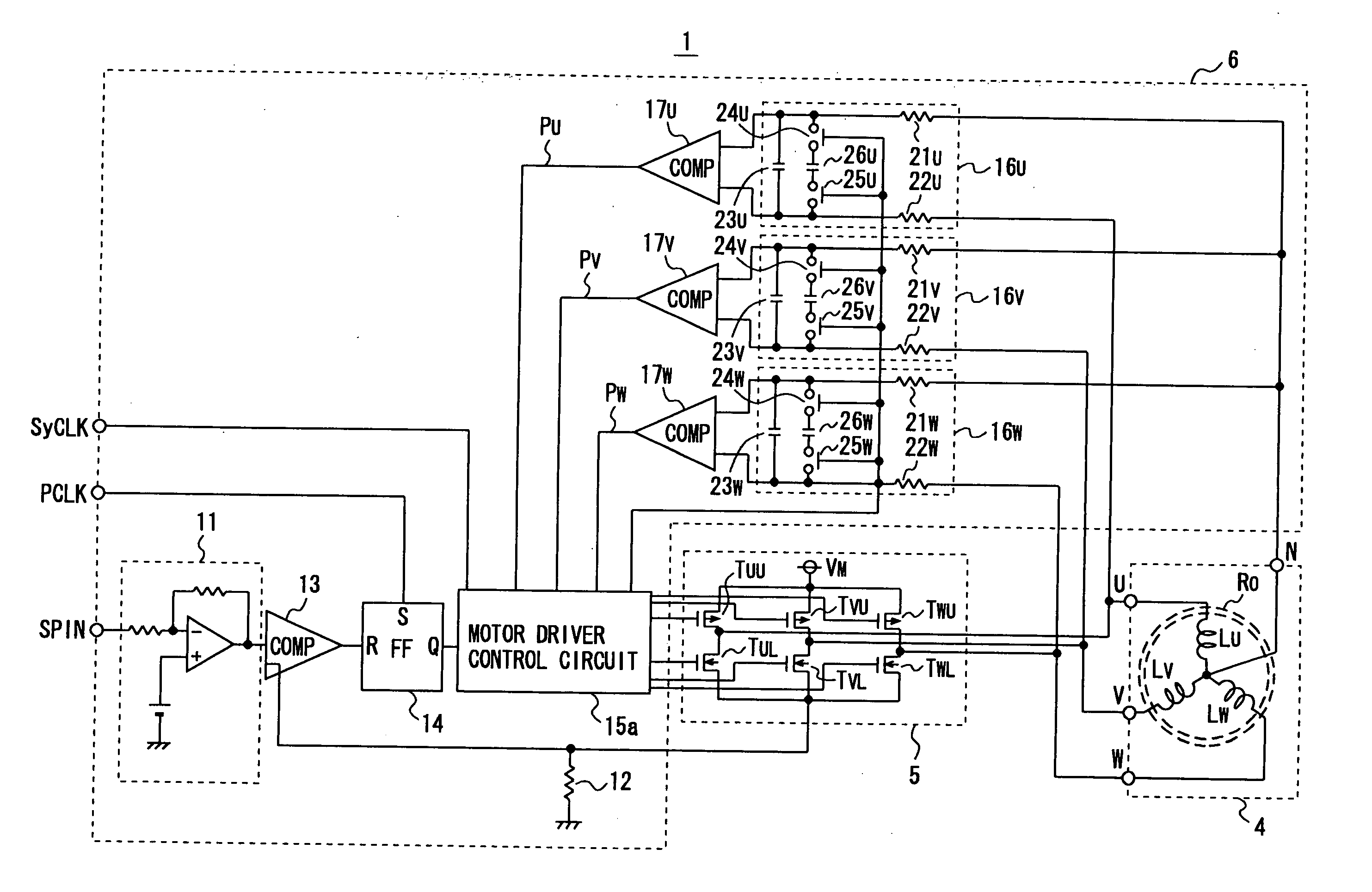
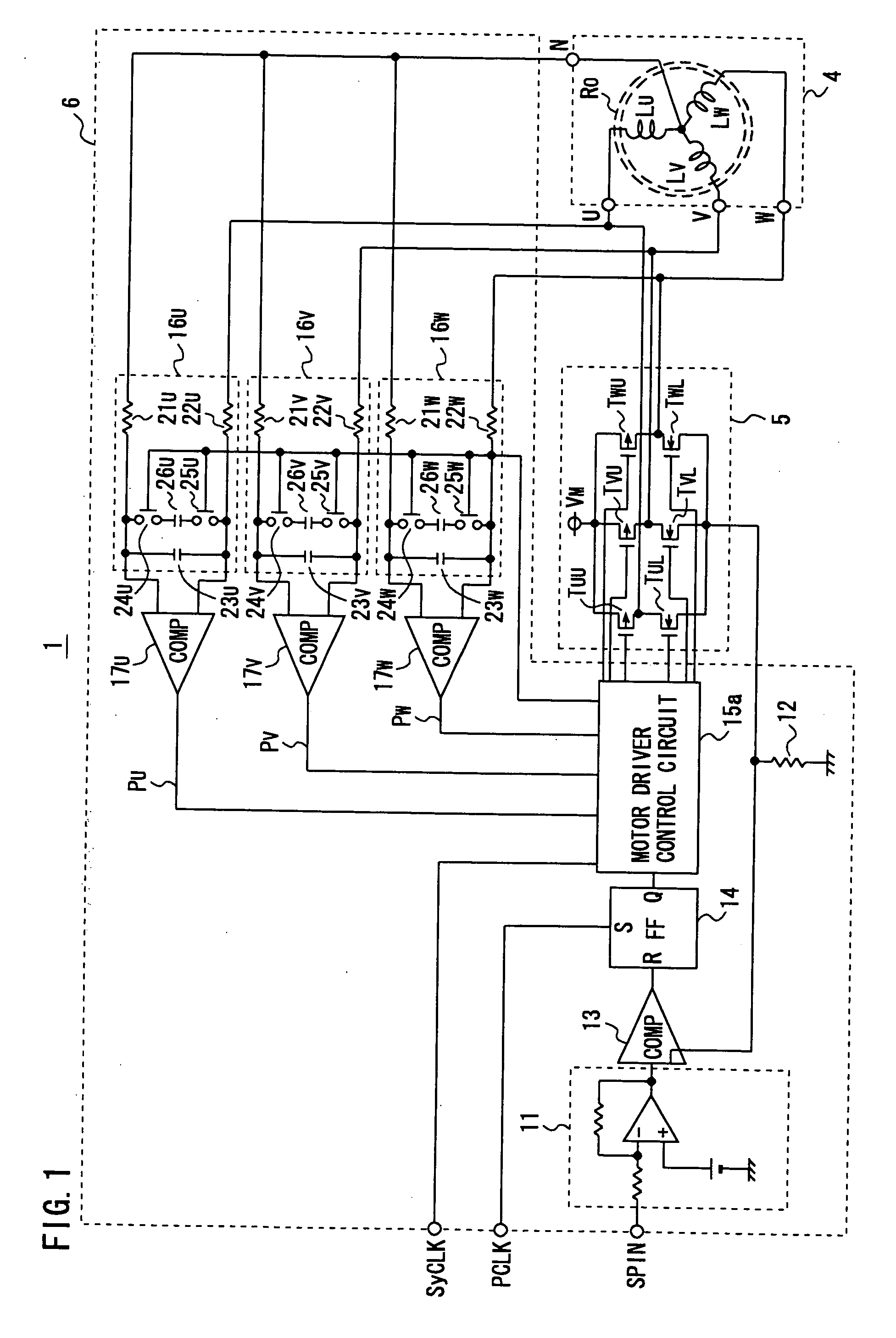
[0019]FIG. 1 is a diagram for use in explaining the brushless motor drive circuit and the brushless motor device using the same according to an embodiment of the present invention.

[0020] With reference to FIG. 1, a brushless motor device 1 according to the embodiment of the present invention includes a brushless motor 4, a motor driver 5 for driving brushless motor 4, and a brushless motor drive control circuit 6 for controlling motor driver 5 as shown in FIG. 1.

[0021] Brushless motor 4 includes a rotor Ro formed of a permanent magnet whose N pole...


PUM


Abstract

There is provided a brushless motor drive control circuit capable of assuring an S / N ratio of a predetermined counter electromotive voltage and suppressing lowering of efficiency of a brushless motor at a high-speed rotation. More specifically, the brushless motor drive control circuit (6) includes: counter electromotive voltage filter circuits (16U, 16V, 16W) for inputting 3-phase counter electromotive voltage induced at the end of each of the stator coils (LU, LV, LW) and switching between a first and a second time constant according to the rotation speed of the rotor (RO) so as to pass a low-range frequency component corresponding to the time constant; counter electromotive voltage detection comparators (17U, 17V, 17W) for inputting the counter electromotive voltage which has passed through the counter electromotive voltage filter circuit and comparing it with voltage at a neutral point so as to output counter electromotive voltage polarity signals (PU, PV, PW) as the comparison results; and a motor driver control circuit (15a) for switching / controlling the time constant of the counter electromotive filter circuits (16U, 16V, 16W) and controlling the motor driver (5) according to the counter electromotive voltage polarity signals.

Description

TECHNICAL FIELD [0001] The present invention relates to a brushless motor drive control circuit for executing sensorless drive control of a brushless motor having a 3-phase stator coil and a brushless motor device using the same. BACKGROUND ART [0002] A brushless motor drive control circuit of this kind controls drive of a brushless motor by detecting a counter electromotive voltage at a 3-phase stator coil generated along with rotation of a rotor by means of a comparator and detecting a rotation position of the rotor based on the counter electromotive voltage without using a hole element (e.g. Japanese Patent Laying-Open No. 8-149879 (Patent Document 1)). [0003] Here, because an amplitude of a counter electromotive voltage generated at the stator coil is proportional to a rotation speed of the rotor, at low-speed rotation, the amplitude of the counter electromotive voltage is smaller as compared with that obtained at high-speed rotation, so that its ratio to noise, that is, an S / N ...

Claims


Application Information

Patent Timeline
IPC IPC(8): H02P7/06H02P6/18H02P6/06H02P6/08H02P6/182
CPCH02P6/182H02P6/002H02P6/28Y02P80/10
Inventor MAEDA, NORIHIRO
Owner ROHM CO LTD
Features
  • Generate Ideas
  • Intellectual Property
  • Life Sciences
  • Materials
  • Tech Scout
  • Unparalleled Data Quality
  • Higher Quality Content
  • 60% Fewer Hallucinations
Learn More