Illumination arrangement for color picture projection

a color picture and projection technology, applied in the field of illumination arrangement, can solve the problems of difficult to house these in the limited space of a device, and the relative size of the system, and achieve the effect of reducing the size of the system and simple resources

Inactive Publication Date: 2007-08-02
CARL ZEISS JENA GMBH
View PDF39 Cites 8 Cited by
  • Summary
  • Abstract
  • Description
  • Claims
  • Application Information

AI Technical Summary

Benefits of technology

[0008] Based on these disadvantages, this invention intends to further develop a lighting arrangement for color image projection by using monochromatic light sources with the goal of allowing for an effective overlapping of light sources while at the same time reducing the size of the system using relatively simple resources.

Problems solved by technology

Arrangements of this type have the disadvantage of being relatively large, and it is often very difficult to house these in the limited space of a device.
Furthermore, the combination of different spectrums also represents high requirements for the color separators used, especially when three or more light sources must be overlapped.

Method used


Image

  • Illumination arrangement for color picture projection
  • Illumination arrangement for color picture projection
  • Illumination arrangement for color picture projection

Examples


Embodiment Construction

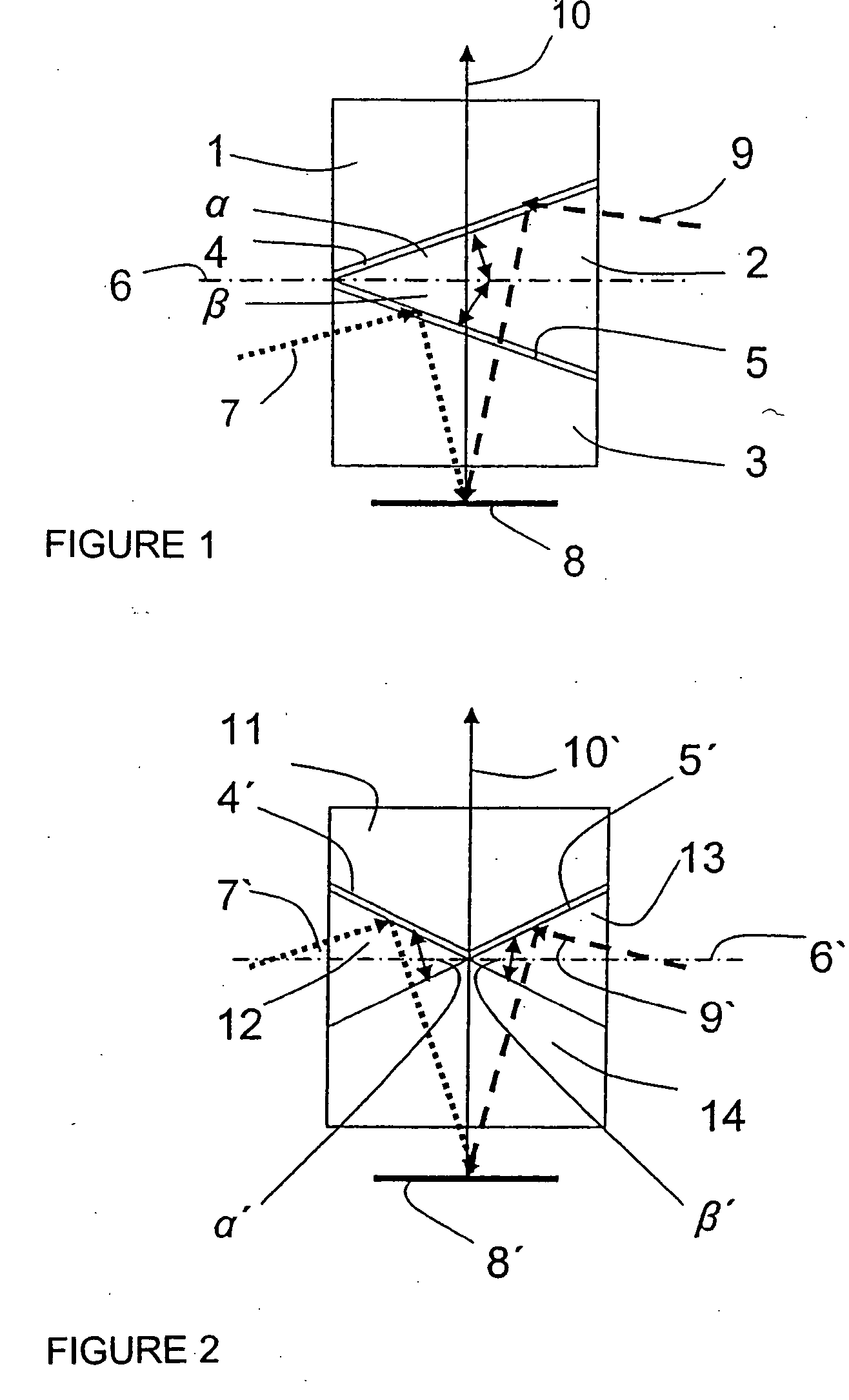
[0030]FIG. 1 shows a combination of three connected prisms 1, 2 and 3, where air gaps 4 and 5 are present between the composite surfaces of prisms 1 and 2 and between prisms 2 and 3. Prisms 1, 2 and 3 are designed so that their composite surfaces have exact opposite angles (β=β) to a reference plane. An optical path 7 from a monochromatic light source, such as the color green, penetrating into prism 3, hits air gap 5 and is reflected by this gap onto an image-forming element 8, such as a DMD. A second optical path 9 of a monochromatic light source, such as a red one, reaches the air gap 9 through prism 2 and is also reflected onto the image-forming element 8. Then, the unification of the two optical paths 7 and 9 takes place at the image-forming element 8 to form the common optical projection path 10. Via a switch arrangement (not pictured), the different monochromatic light sources can be switched on and off, so that the different color channels can be modulated separately. The tri...


PUM


Abstract

This invention involves a lighting arrangement for color image projection with at least two lighting units, whose light will hit image-forming elements, such as DMDs or grating light valves via optical elements, so that a subsequent optical projection system will project a multi-colored image on a projection surface. This invention shows that the illuminating optical paths will hit one or more image-forming elements from different directions and that once they pass the image-forming element or elements, they will be combined into one common optical projection path.

Description

RELATED APPLICATION [0001] The present application claims the benefit of priority to German Patent Application No. 10 2005 061 182.6 filed on Dec. 21, 2005. Said application is incorporated by reference herein. FIELD OF THE INVENTION [0002] The invention relates to lighting arrangement to project color images with at least two lighting units via optical elements. The light passes through image-forming modulators, such as DMDs or grating light valves via optical elements, so that a subsequent optical projection system will project a multi-colored image on a projection surface. BACKGROUND OF THE INVENTION [0003] There are a number of known lighting arrangements for color image projection, which use only one image-forming element (single-chip arrangement) or multiple image forming elements (multi-chip arrangements). [0004] DE 10127617 A1, for example, describes a projection arrangement with one lighting unit to create an illuminated field. Here, an image-forming element (light modulato...

Claims


Application Information

Patent Timeline
Patent Type & Authority Applications(United States)
IPC IPC(8): G03B21/26
CPCG02B27/1026G02B27/1033G02B27/126H04N9/3197H04N9/3105H04N9/315G02B27/145
Inventor PIEHLER, EBERHARD
Owner CARL ZEISS JENA GMBH
Why Eureka
Try Eureka