

Lighting for insulated glazing assembly
a technology of insulated glazing and assembly, which is applied in the direction of fixed installation, lighting elements, lighting and heating equipment, etc., can solve the problems of reducing the visibility of decorative panels, unreliable natural light, and unsatisfactory krause in some ways
- Summary
- Abstract
- Description
- Claims
- Application Information
AI Technical Summary
Benefits of technology
Problems solved by technology
Method used
Image

Examples
third embodiment
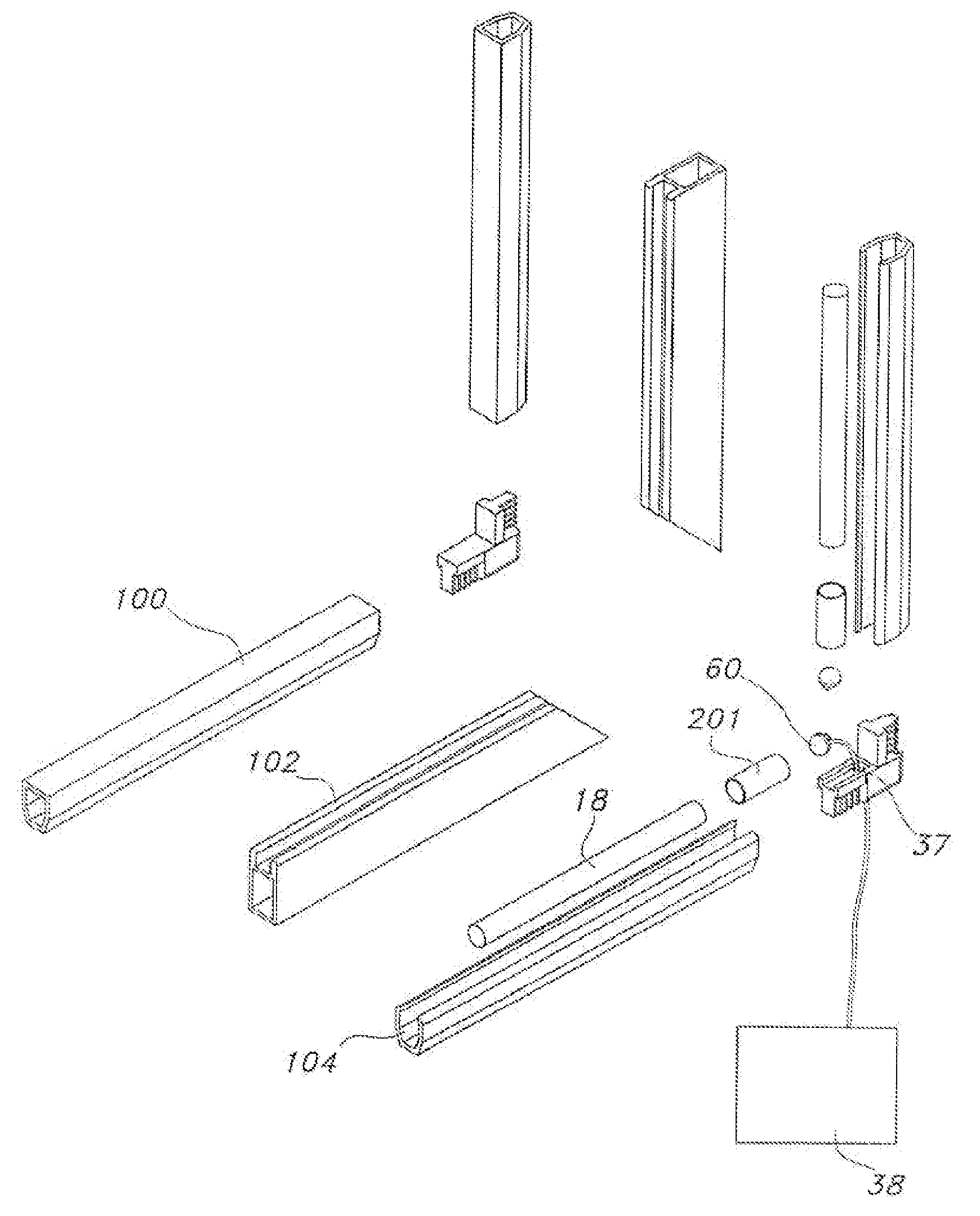
[0060] A third embodiment positions a light source or light guide on a retractable shade system, as shown in FIG. 8A, or louver system, as shown in FIG. 8B, mounted inside the IG assembly—each of which are described in more detail below.
[0061] In the retractable shade embodiment shown in FIG. 8A a retractable shade 802 is installed within an IG assembly using known techniques for installing a retractable shade. The retractable shade system 802 includes a light source 804 which directs light substantially in one direction such that panel 806 of the IG assembly is lit and panel 808 of the IG assembly is unlit and blocked by the substantially opaque shade 810. The light source 804 may be an electroluminescence (“EL”) panel, EL strip, or essentially any other suitable light source. In one embodiment, an EL panel is laminated to and covers the full shade 810. Power may be provided to the light source 804 through the spacer assembly as described above. In one embodiment, power to the ligh...
fourth embodiment
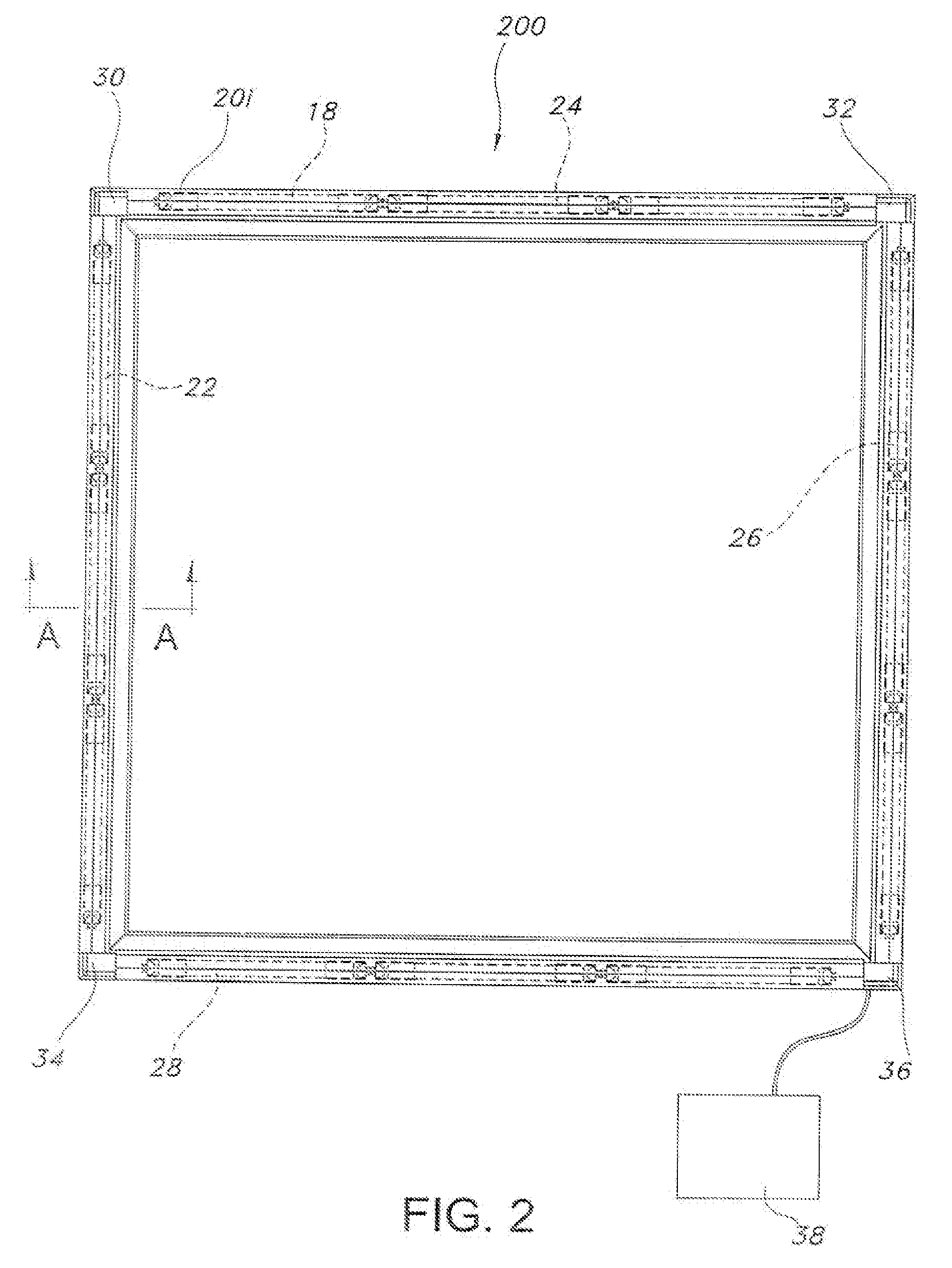
[0063] A fourth embodiment features a light source mounted to a panel within the IG assembly. For example, an EL source mounted to a caming or mullion as shown in FIGS. 9A and 9B, a light source directly mounted to a panel as shown in FIG. 12, a light source corner mounted to a caming as shown in FIG. 13—each of which are discussed in more detail below.
[0064] The EL source embodiments shown in FIGS. 9A and 9B include an IG assembly with a first panel 902, a second panel 904, and an intermediate panel 906 mounted between. The intermediate panel 906 includes either a caming 908, shown in FIG. 9A or a mullion 910, shown in FIG. 9B. An EL source 912, such as a wire or strip, is mounted using the caming 908 or mullion 910. The EL source 912 may be augmented with reflectors, light guides, lenses, or other light manipulators to achieve a desired lighting effect. Optionally, the EL source 912 may be hidden behind an etched or textured pattern. Power may be provided to the EL source through ...
fifth embodiment
[0067] A fifth embodiment features a light manipulator mounted to a panel within the IG assembly. For example, a light guide mounted to a caming or mullion as shown in FIGS. 10A, 10B, and 10C, a fiber optic wire mounted to a panel as shown in FIGS. 11A and 11B, or a ultraviolet (“UV”) coating as shown in FIG. 17—each of which are discussed in more detail below. In these light manipulator embodiments the light source may be mounted in a variety of configurations and positions depending on the desired lighting and type of light source.
[0068] The light guide embodiments shown in FIGS. 10A, 10B, and 10C include an IG assembly with a first panel 1002, a second panel 1004, and an intermediate panel 1006 mounted between. One or more light sources 1012 are mounted to the closure 1014. One or more light guides 1016 are mounted to the caming 1008, shown in FIG. 10A, mullion 1010, shown in FIG. 14, or panel 1006, shown in FIG. 10B and FIG. 15. The light guides 1016 may be plastic, glass, or an...
PUM
 Abstract
Description
Claims
Application Information