
Reduction of pulse width by spectral broadening in amplification stage and after amplification stage

a fiber laser and spectral broadening technology, applied in the field of fiber laser systems, can solve the problems of limited cpa systems, limited cpa systems, and limited ordinary skill in the art, so as to reduce the width of pulses, increase the spectral bandwidth, and broaden the spectral bandwidth

Active Publication Date: 2007-08-02
POLARONYX
View PDF6 Cites 9 Cited by
  • Summary
  • Abstract
  • Description
  • Claims
  • Application Information

AI Technical Summary

Benefits of technology

[0008]It is therefore an aspect of the present invention to provide a laser system for reducing the pulse width by increasing the pulse spectral bandwidth wherein the spectral bandwidth is broadened by taking advantage of the SPM effects. The laser transmission with broadened spectrum can be amplified without suffering the gain narrowing effects such that the above-discussed difficulties of spectral narrowing effect during the pulse amplifications as that encountered in the prior art may be resolved.
[0010]Another aspect of this invention is to provide a laser system for reducing the pulse width by increasing the pulse spectral bandwidth by taking advantage of the SPM that may take place in wide varieties of fibers. The system is therefore implemented with amplifiers that have the amplifier gains that would be wide enough to support the broadened spectrum by the SPM effects.
[0011]Another aspect of this invention is to provide a laser system for reducing the pulse width by increasing the pulse spectral bandwidth by taking advantage of the SPM that may take place after the amplification stage such that the broadening spectrum will not be limited by the gain spectrum of the amplifier. The length of the fiber implemented after the amplification stage should have appropriate length in order to generate the required spectrum bandwidth without having serious wave breaking effect

Problems solved by technology

Even though current technologies of fiber laser have made significant progress toward achieving a compact and reliable fiber laser system providing high quality output laser with ever increasing output energy, however those of ordinary skill in the art are still confronted with technical limitations and difficulties.
The broadened pulse width thus increases the difficulties of generating the high-energy laser of short pulse lasers, e.g., a laser with a femtosecond pulse width.
Furthermore, in a fiber laser system implemented with the Chirped Pulse Amplification (CPA) for short pulse high power laser amplifier, the CPA systems are still limited by the technical difficulties that the third order dispersion (TOD) limits the scalability of the laser systems.
Such limitations were not addressed in the conventional technologies due to the fact that the conventional solid-state laser utilizes Grating-Lens combination and Treacy compressor for pulse stretching and compressing.
Ideally, in such solid-state systems, all orders of dispersion can be compensated, but the material dispersion can distort and damage this ideal situation.
However, for a fiber laser system, the situation is different due to the fact that in the fiber laser systems, attempts are made by using the fiber stretcher to replace the grating-lens combination for the purpose of significantly increasing the system reliability.
However, the TOD limits the ability for de-chirping when using Treacy compressor since both fiber stretcher and Treacy compressor have positive TOD even this combination can remove the second order dispersion completely.
This issue of TOD dispersion makes it more difficult to develop a high-energy fiber laser amplifier with <200 fs pulse width.
Actually, the technical difficulty of TOD dispersion is even more pronounced for laser system of higher energy.
Therefore, for laser system of higher energy, it is even more difficult to re-compress the pulse to the original pulse width.
However, the issue of generating a short pulse width in a fiber laser system is always difficult to achieve due to an uncompensated highly positive third-order dispersion (TOD) generally referred to as the compressibility issue.
However, in practice, this conventional dogmatic design concept is no longer considered as universally acceptable.
The concept of applying the phase shift and spectral generation for improvement of pulse quality as that disclosed in a fiber Raman amplifier does not provide a direct solution to the difficulties caused by the compressibility issues due to the technical challenges arise from the third order dispersion effects.

Method used


Image

  • Reduction of pulse width by spectral broadening in amplification stage and after amplification stage
  • Reduction of pulse width by spectral broadening in amplification stage and after amplification stage
  • Reduction of pulse width by spectral broadening in amplification stage and after amplification stage

Examples


Embodiment Construction

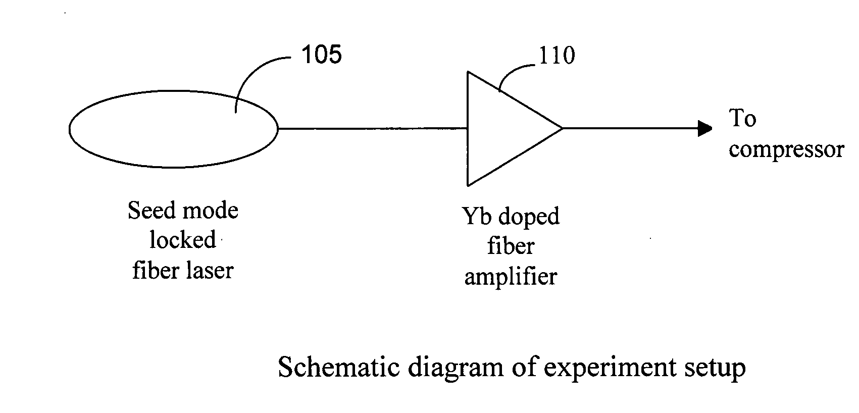
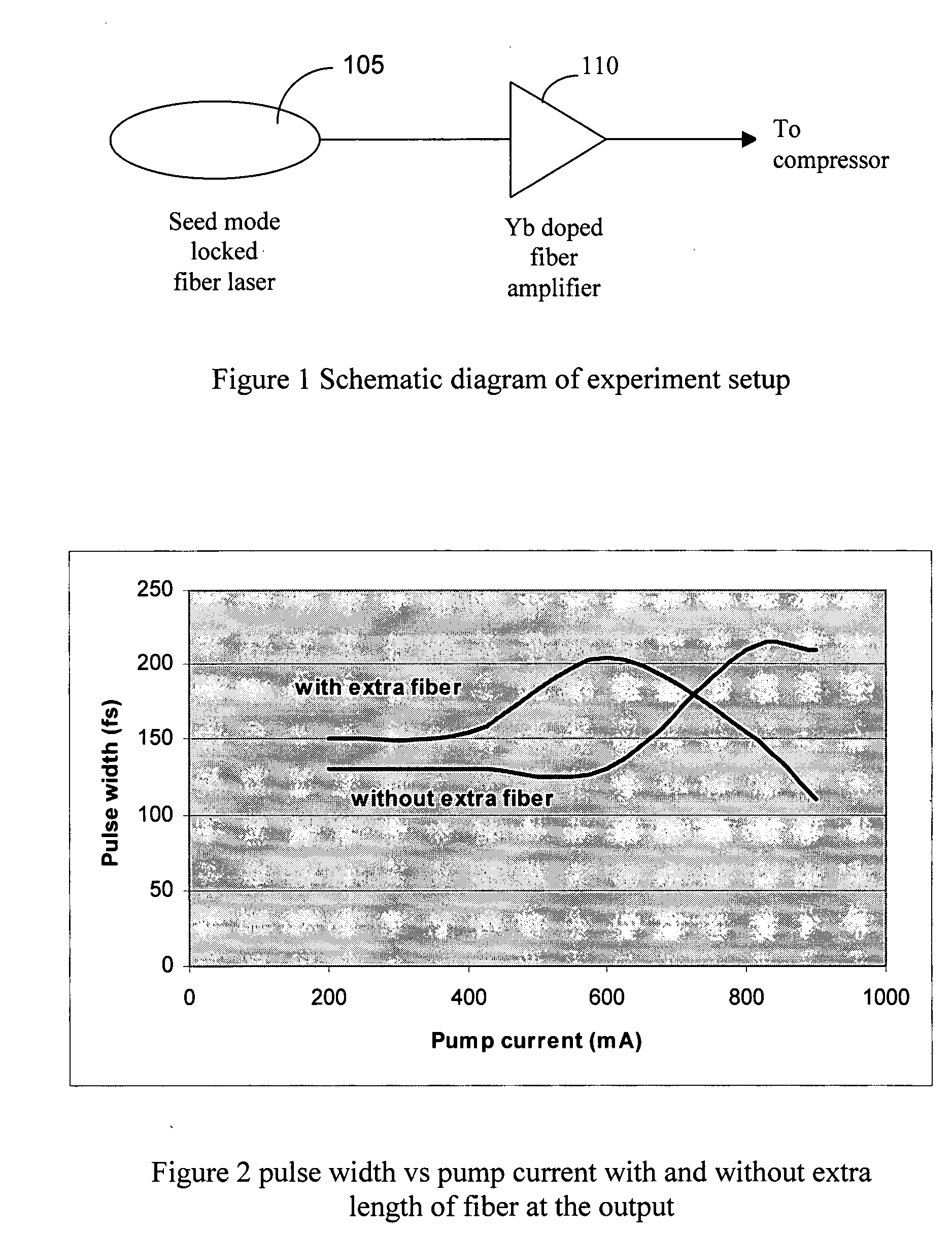
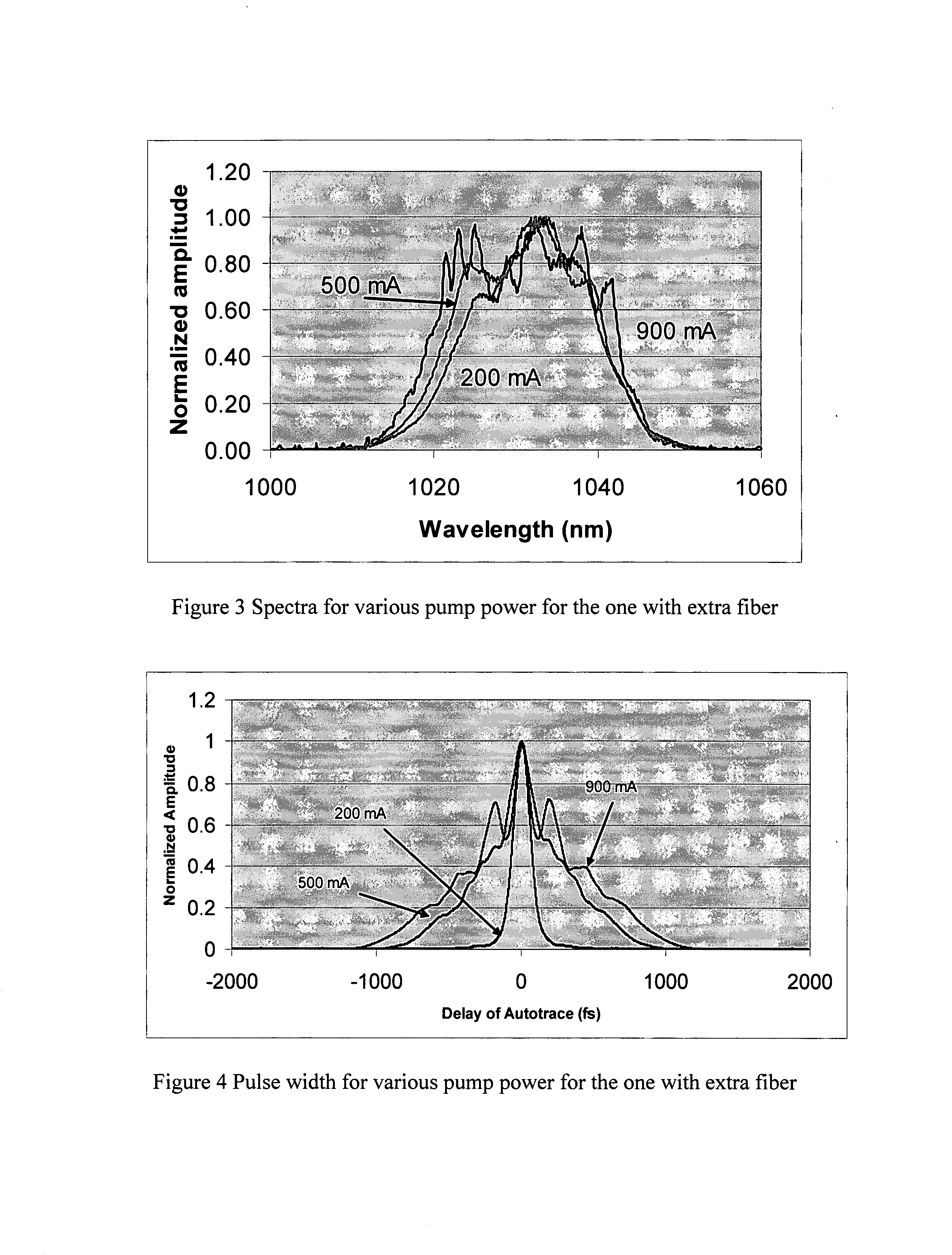
[0019]Referring to FIG. 1 for a schematic diagram of a laser system 100 that is implemented for taking advantage of the SPM spectral broadening technique of this invention. The laser system 100 includes a laser seed 105 for generating a seed laser. The seed laser 105 is a mode locked fiber laser operating at 1030 nm spectral with about 3 mW of power for projecting a laser into a fiber amplifier 110 using a Yb doped fiber. The seed laser is first stretched to 10 ps pulses before the laser is projected to the amplifier 110. A grating compressor (not shown) is used to compress the laser pulse after amplifier 110. The amplifier output an average power up to 250 mW. FIG. 2 shows that when the length of fiber 120 after the amplifier 110 is 2 m at the output, the pulse width can be reduced significantly because of the SPM induced spectrum broadening. FIG. 2 also shows that the SPM effects distort and broaden the pulse width where there is not enough spectrum broadening. As shown in FIG. 2,...


PUM


Abstract

This invention discloses a fiber Chirped Pulse Amplification (CPA) laser system. The system includes a fiber mode-locking oscillator for generating a seed laser. The laser system further includes a stretching stage for stretching the seed laser for projecting to an Yb doped amplifier. The Yb doped amplifier is implemented for taking advantage of a self phase modulation (SPM) to broaden a spectrum whereby an amplification of the laser pulse is without narrowing down the spectrum. The amplifier has a gain spectrum corresponding to a broaden spectrum by taking advantage of the SPM in the amplifier. The amplifier is further connected to an output fiber having a predefined length with a predefined level of SPM for broadening a spectrum.

Description

[0001]This Formal Application claims a Priority Date of Feb. 1, 2006 benefit from a Provisional Patent Application 60 / 765,600 filed by the one common Inventor of this application. The disclosures made in 60 / 765,600 are hereby incorporated by reference in this patent application.FIELD OF THE INVENTION[0002]The present invention relates generally to apparatuses and methods for providing fiber laser system. More particularly, this invention relates a system configuration by applying a SPM spectral broadening technique for reducing the pulse width in the amplification stage and after the amplification stage.BACKGROUND OF THE INVENTION[0003]Even though current technologies of fiber laser have made significant progress toward achieving a compact and reliable fiber laser system providing high quality output laser with ever increasing output energy, however those of ordinary skill in the art are still confronted with technical limitations and difficulties. Specifically, when a short pulse h...

Claims


Application Information

Patent Timeline
Patent Type & Authority Applications(United States)
IPC IPC(8): H01S3/13
CPCH01S3/0057H01S3/1618H01S3/06754H01S3/06725
Inventor LIU, JIAN
Owner POLARONYX
Learn More