
Integrated circuit arrangement for converting a high-frequency bandpass signal to a low-frequency quadrature signal

a technology of integrated circuit and high-frequency bandpass, which is applied in the direction of modulated carrier systems, transmission, angle demodulation, etc., can solve the problems of high power consumption during operation, energy consumption of the hf front-end circuit, and high current consumption in assemblies, which are operated at frequencies in the gigahertz range, and achieve energy-efficient and powerful transmitting/receiving, simple implementation, and energy-efficient operation

Inactive Publication Date: 2007-08-02
ATMEL AUTOMOTIVE
View PDF14 Cites 27 Cited by
  • Summary
  • Abstract
  • Description
  • Claims
  • Application Information

AI Technical Summary

Benefits of technology

[0014]It is therefore an object of the present invention to provide an integrated HF front-end circuit arrangement, which is energy-efficient to operate and simple to implement, so that energy-efficient and powerful transmitting / receiving devices, which are cost-effective to realize, are made possible.

Problems solved by technology

Furthermore, the current consumption in assemblies, which are operated at frequencies in the gigahertz range, is much higher than in the assemblies which are operated at lower frequencies.
For these reasons, the energy consumption of the HF front-end circuit arrangement is very important for the energy consumption of the entire transmitting / receiving device.
A disadvantage here is the high power consumption during operation and the increased implementation cost.

Method used


Image

  • Integrated circuit arrangement for converting a high-frequency bandpass signal to a low-frequency quadrature signal
  • Integrated circuit arrangement for converting a high-frequency bandpass signal to a low-frequency quadrature signal
  • Integrated circuit arrangement for converting a high-frequency bandpass signal to a low-frequency quadrature signal

Examples


Embodiment Construction

[0034]In the figures, the same and functionally identical elements and signals, if not specified otherwise, are provided with the same reference characters.

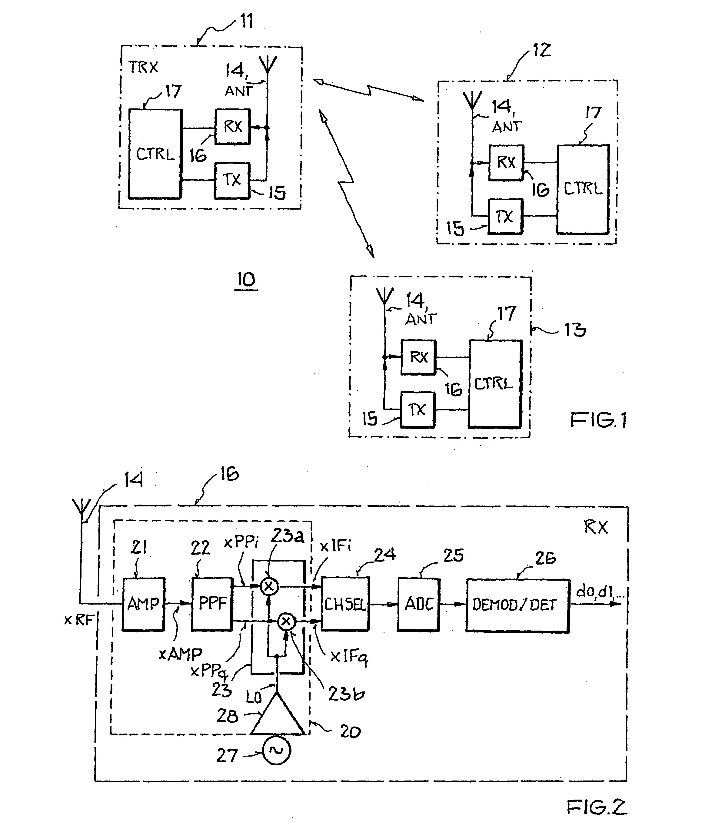
[0035]FIG. 1 shows an example of a “Wireless Personal Area Network” (WPAN) 10 according to IEEE standard 802.15.4. It comprises three transmitting / receiving devices (transceiver, TRX) 11-13 in the form of stationary or mobile devices, which exchange information in a wireless manner by means of radio signals. Transmitting / receiving device 11 is a so-called full-function device, which takes on the function of the WPAN coordinator, whereas transmitting / receiving devices 12, 13 are so-called reduced-function devices, which are assigned to full-function device 11 and can only exchange data with said device. Apart from the star network topology depicted in FIG. 1, in which bidirectional data transmission can only occur between one of the reduced-function devices 12, 13 and the full-function device 11, but not between reduced function d...


PUM


Abstract

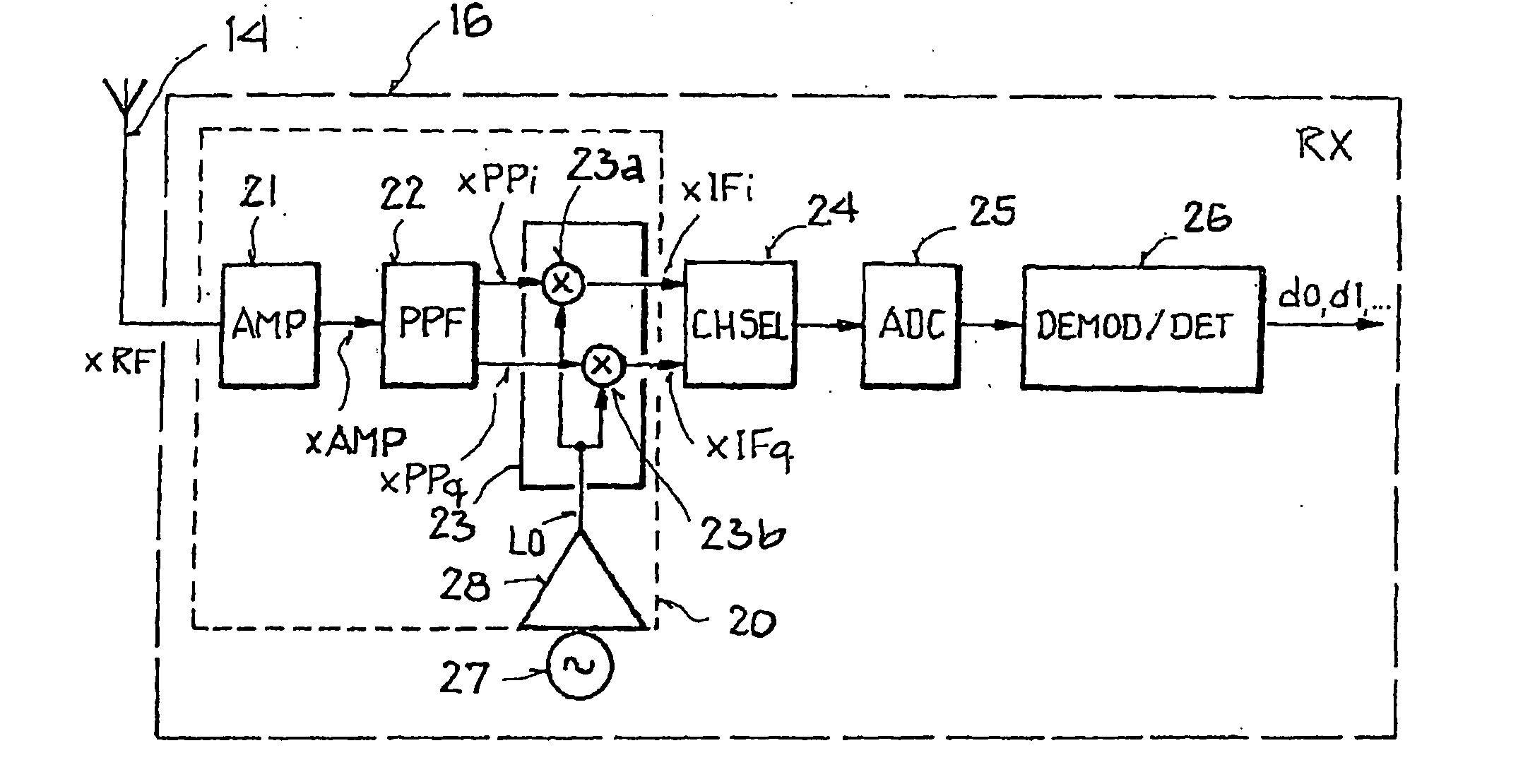
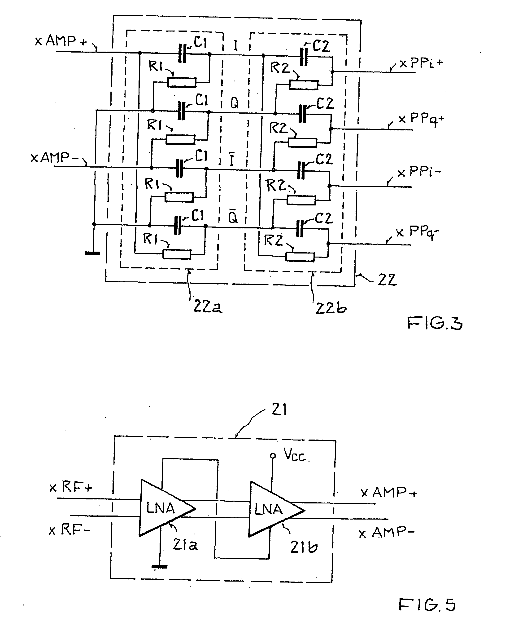
An integrated circuit arrangement is provided for converting a high-frequency bandpass signal to a low-frequency quadrature signal with a first in-phase component and a first quadrature-phase component, which has: an amplifier arrangement, which is designed to generate an amplified signal and has a first amplifier stage for amplifying the high-frequency bandpass signal, a mixer unit with a first mixer to provide the first in-phase component and a second mixer to provide the first quadrature-phase component, and a driver amplifier, which is designed to generate a local oscillator signal. According to the invention, between the amplifier arrangement and the mixer unit a polyphase filter is disposed, which converts the amplified signal to a complex-valued polyphase signal with a second in-phase component and a second quadrature phase component. Furthermore, according to the invention each mixer is connected to the driver amplifier, and the first mixer is designed to multiply the second in-phase component by the local oscillator signal, and the second mixer is designed to multiply the second quadrature-phase component by the local oscillator signal.

Description

[0001]This nonprovisional application claims priority under 35 U.S.C. § 119(a) on German Patent Application No. 102006004951, which was filed in Germany on Feb. 1, 2006, and which is herein incorporated by reference.BACKGROUND OF THE INVENTION[0002]1. Field of the Invention[0003]The present invention relates to an integrated circuit arrangement for converting a high-frequency bandpass signal to a low-frequency quadrature signal. The invention relates furthermore to a transmitting / receiving device with a circuit arrangement of this type.[0004]2. Description of the Background Art[0005]The invention is in the field of communication systems, in which a plurality of transmitting / receiving devices access a specific frequency band or carrier frequency channels contained therein. It is particularly in the field of integrated circuits, with whose help in such transmitting / receiving devices on the receiver side a high-frequency bandpass signal, such as, e.g., a radio signal received via an an...

Claims


Application Information

Patent Timeline
IPC IPC(8): H04L27/22
CPCH03D7/1441H03D7/1408H03D7/165H03D7/1466H03D7/1483H03D7/1458
Inventor KLUGE, WOLFRAM
Owner ATMEL AUTOMOTIVE
Learn More