Vertical axis wind turbine and wind turbine blade

Inactive Publication Date: 2007-08-02
INTPROP BANK CORP (JP)
View PDF5 Cites 51 Cited by
  • Summary
  • Abstract
  • Description
  • Claims
  • Application Information

AI Technical Summary

Benefits of technology

[0040] According to the present invention, since the vertical axis wind turbine featured by comprising the wind receiving plate having the wind receiving surface and the openable and closable pivot, which wind receiving plate is operated to close in the direction in which the centrifugal force is produced in proportion to the revolution of the blade generating the lifting power, and the energizing means for energizing the opening force to open the wind receiving plate to the wind receiving side, the starting performance of the lift type wind turbine can be improved by means of the wind receiving plate, which opens at a low revolution of the blade so as to function as a drag type wind turbine, and automatically closes at a high revolution of the blade so as to function as a lift type wind turbine, consequently to switch between the drag type wind turbine and lift type wind turbine with a simple structure by the action of the structure of closing the wind receiving plate with the centrifugal force.
[0041] Also, according to the present invention, since the blade of the invention is provided with the wind receiving plate having the wind receiving surface and the openable and closable pivot, which wind receiving plate is operated to close in the direction in which the centrifugal force is produced in proportion to the revolution of the blade generating the lifting power, and the energizing means for energizing the opening force to open the wind receiving plate to the wind receiving side, the wind receiving plate having a large wind receiving area can be used, consequently to improve the starting performance of the lift type wind turbine.
[0042] Since the pr

Problems solved by technology

However, since the invention disclosed in Patent Literature 1 provides a mechanism for producing a rotating moment on the blade with the air resistance caused by the cutout in the lower wing part of the blade at a l

Method used


Image

  • Vertical axis wind turbine and wind turbine blade
  • Vertical axis wind turbine and wind turbine blade
  • Vertical axis wind turbine and wind turbine blade

Examples


Embodiment Construction

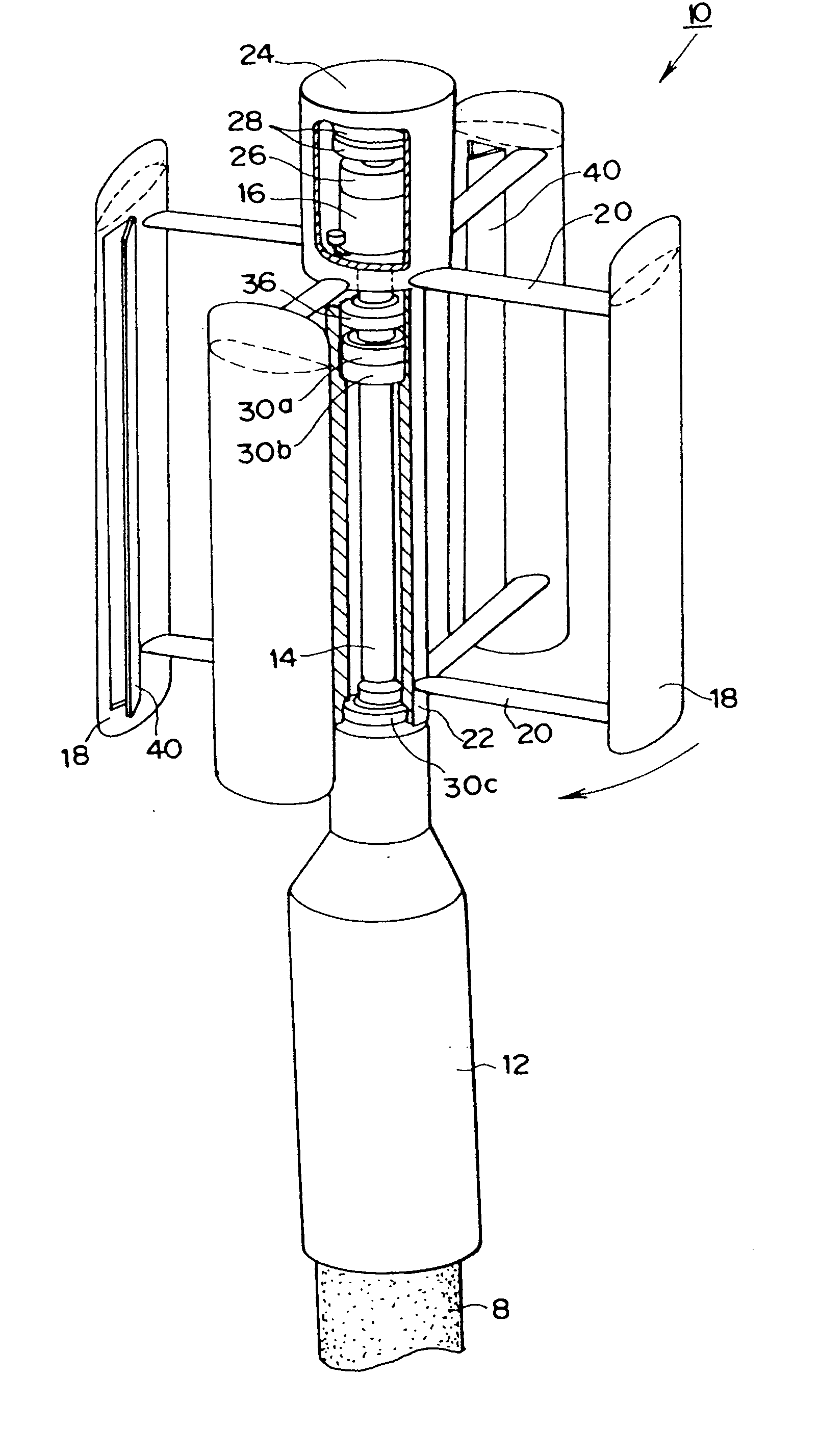
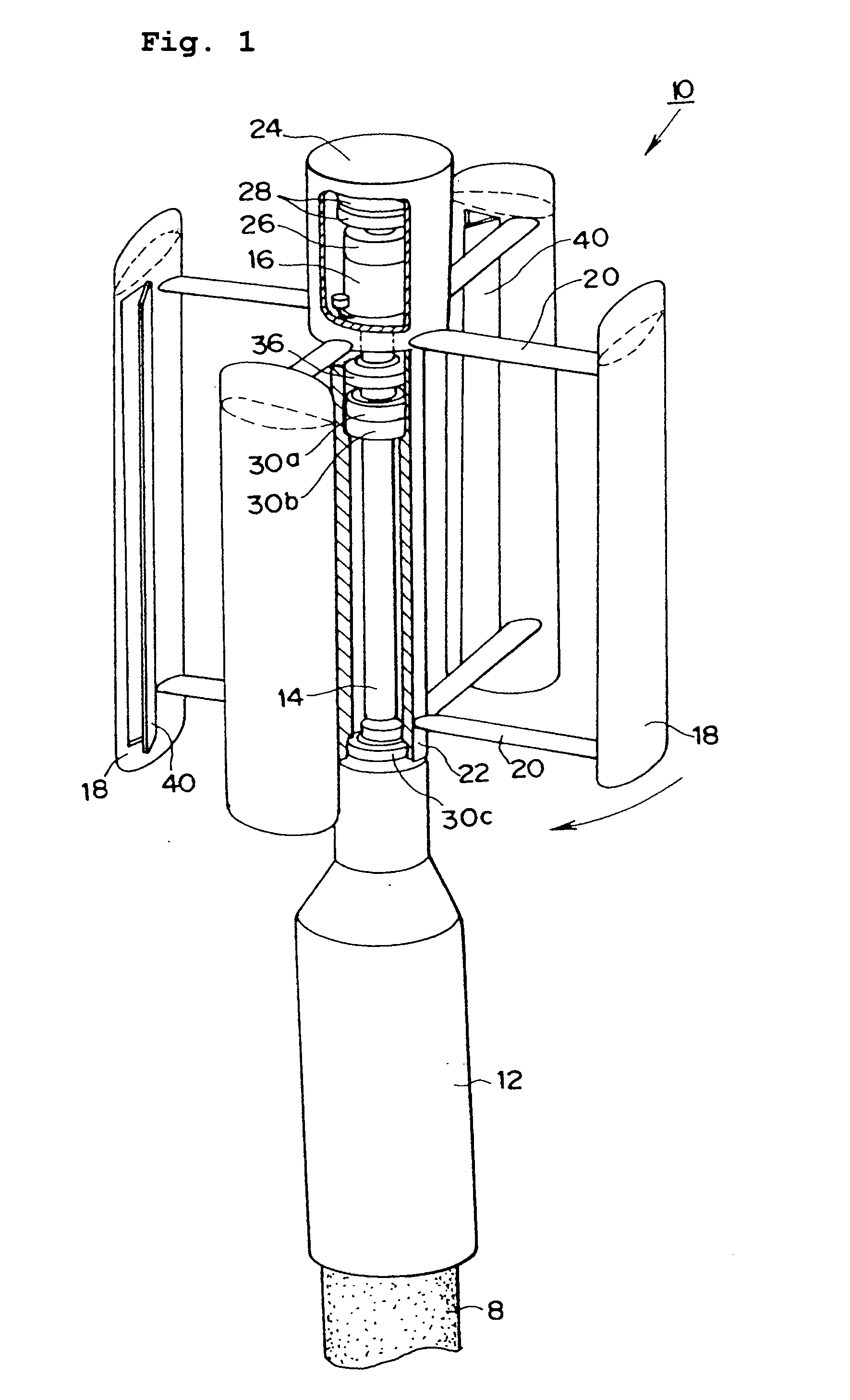
[0080] The vertical axis wind turbine and wind turbine blade according to the present invention will be described hereinafter. FIG. 1 is a perspective view showing the appearance of the vertical axis wind turbine and wind turbine blade of the invention.

[0081] As shown in the drawing, the vertical axis wind turbine 10 comprises a mount portion 12 attached to an electric pole or other pole 8, a fixing shaft 14 fixed onto the mount portion 12, a generator 16 disposed on the top end of the fixing shaft 14, a blade 18 generating rotational torque by converting a wind velocity to lifting power, a support arm having a streamline section for supporting the blade at its upper and lower ends, an outer sleeve 22 attached to the support arm 20, and a torque transmission cap 24 for transmitting the rotational torque of the outer sleeve 22 to the generator 16.

[0082] In the illustrated embodiment, a speed-up device is mounted on the input shaft of the generator 16, so that the revolution of the ...


PUM


Abstract

It is an object of the invention is to provide a vertical axis wind turbine and a wind turbine blade, which are excellent in self-starting performance and have a high torque constant.
Since the present invention comprises a wind receiving plate 40 having a wind receiving surface and an openable and closable pivot 42, which wind receiving plate 40 is operated to close in the direction in which the centrifugal force is produced in proportion to the revolution of a blade 18 generating a lifting power, and an energizing means (such as spring 44) for energizing an opening force to open the wind receiving plate to the wind receiving side, the starting performance of the lift type wind turbine can be improved by means of the wind receiving plate 40, which opens at a low revolution of the blade 18 so as to function as a drag type wind turbine, and automatically closes at a high revolution of the blade 18 so as to function as a lift type wind turbine.

Description

TECHNICAL FIELD [0001] This invention relates to a starting mechanism for a lift type wind turbine. BACKGROUND ART [0002] A straight-wing type vertical axis wind turbine is a wind turbine, which operates in principle in the energy-efficient form of a lifting power similarly to a horizontal-axis propeller type wind turbine and a Darius-type wind turbine, but the wind turbine of this type has some advantages suitable to a small wind power generator capable of generating a rated output of 100 W to several tens kW depending on its shape. Meanwhile, it suffers from the disadvantage of inferior self-starting capability in a slight wind of about 1 to 3 m / s. [0003] As a wind turbine excellent in self-starting capability, there has been a wind turbine employing a wing utilizing a drag principle as typified by a Sabonius wind turbine, whereas the drag type wind turbine which operates by the pressure of wind is extremely inefficient in conversion efficiency of the energy gained from the wind, ...

Claims


Application Information

Patent Timeline
IPC IPC(8): F03D7/06F03D3/00F03D3/06F03D11/00
CPCF03D3/005Y02E10/74F05B2240/214F03D7/06
Inventor YOKOI, TADASHI
Owner INTPROP BANK CORP (JP)
Why Eureka
Try Eureka