Stationary blade ring of axial compressor

a compressor and blade technology, applied in the direction of machines/engines, stators, liquid fuel engines, etc., can solve the problems of low damping effect in response to blade vibration, possibility of cracking starting in the fillet weld zone, notch defect in the bottom of a welded overlay, etc., to enhance the reliability of the compressor, eliminate the possibility of cracking, and prolong the interval between periodic inspections

Active Publication Date: 2007-08-02
MITSUBISHI POWER LTD
View PDF17 Cites 46 Cited by
  • Summary
  • Abstract
  • Description
  • Claims
  • Application Information

AI Technical Summary

Benefits of technology

[0019]According to the compressor stationary blade ring of the gas turbine of the present invention, the built-up stationary blades can be achieved, and fillet welding can be abolished. This eliminates the possibility for cracking, and enhances the reliability of the compressor. Moreov

Problems solved by technology

In welding, a notch defect may occur in the bottom of a welded overlay.
This tendency is strong with fillet welding of this example, where there is a possibility for the occurrence of cracking starting in the fillet weld zones.
This has caused the

Method used


Image

  • Stationary blade ring of axial compressor
  • Stationary blade ring of axial compressor
  • Stationary blade ring of axial compressor

Examples


embodiment 1

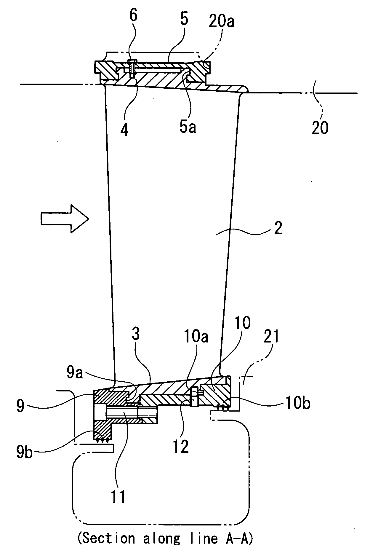
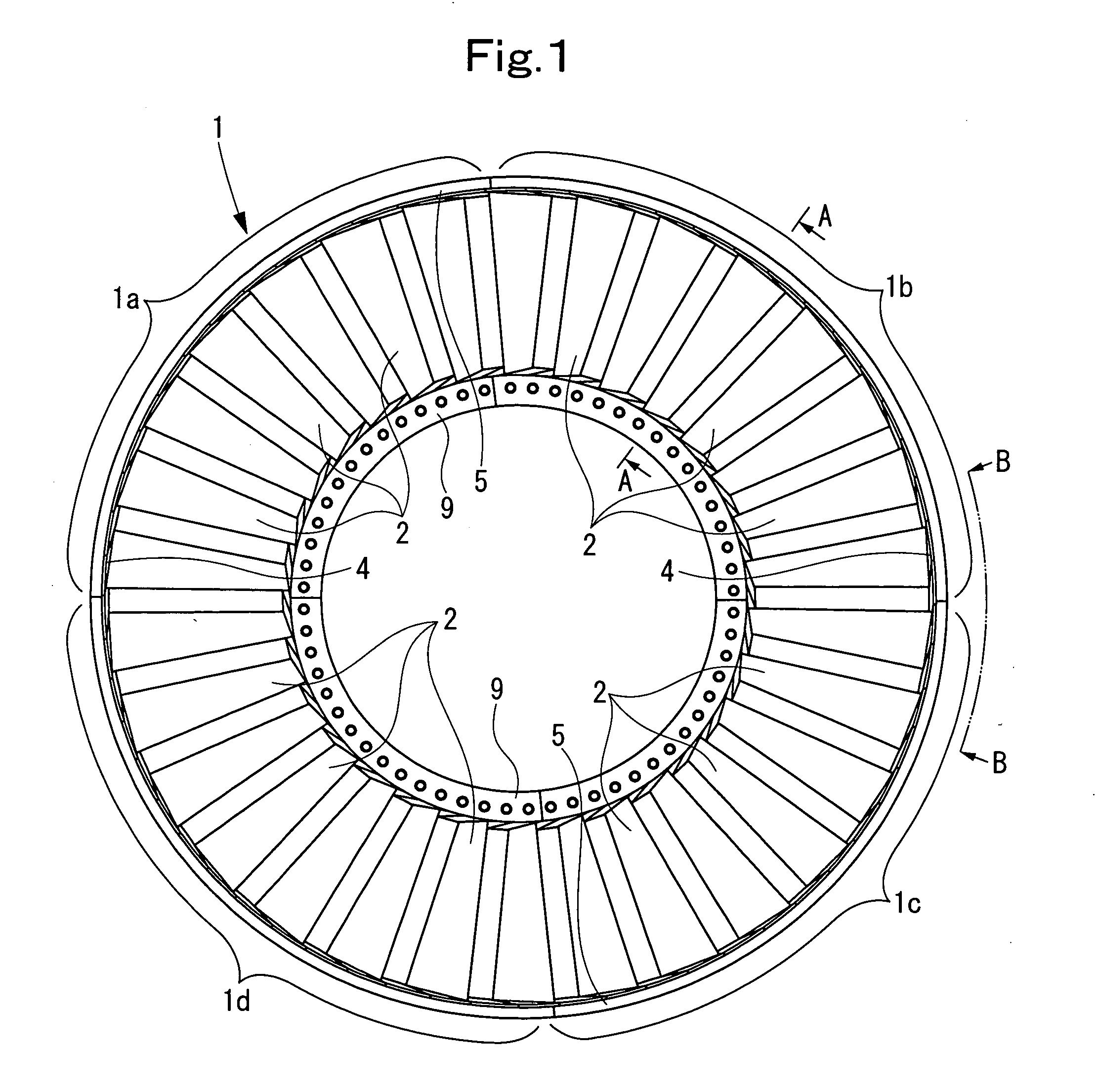
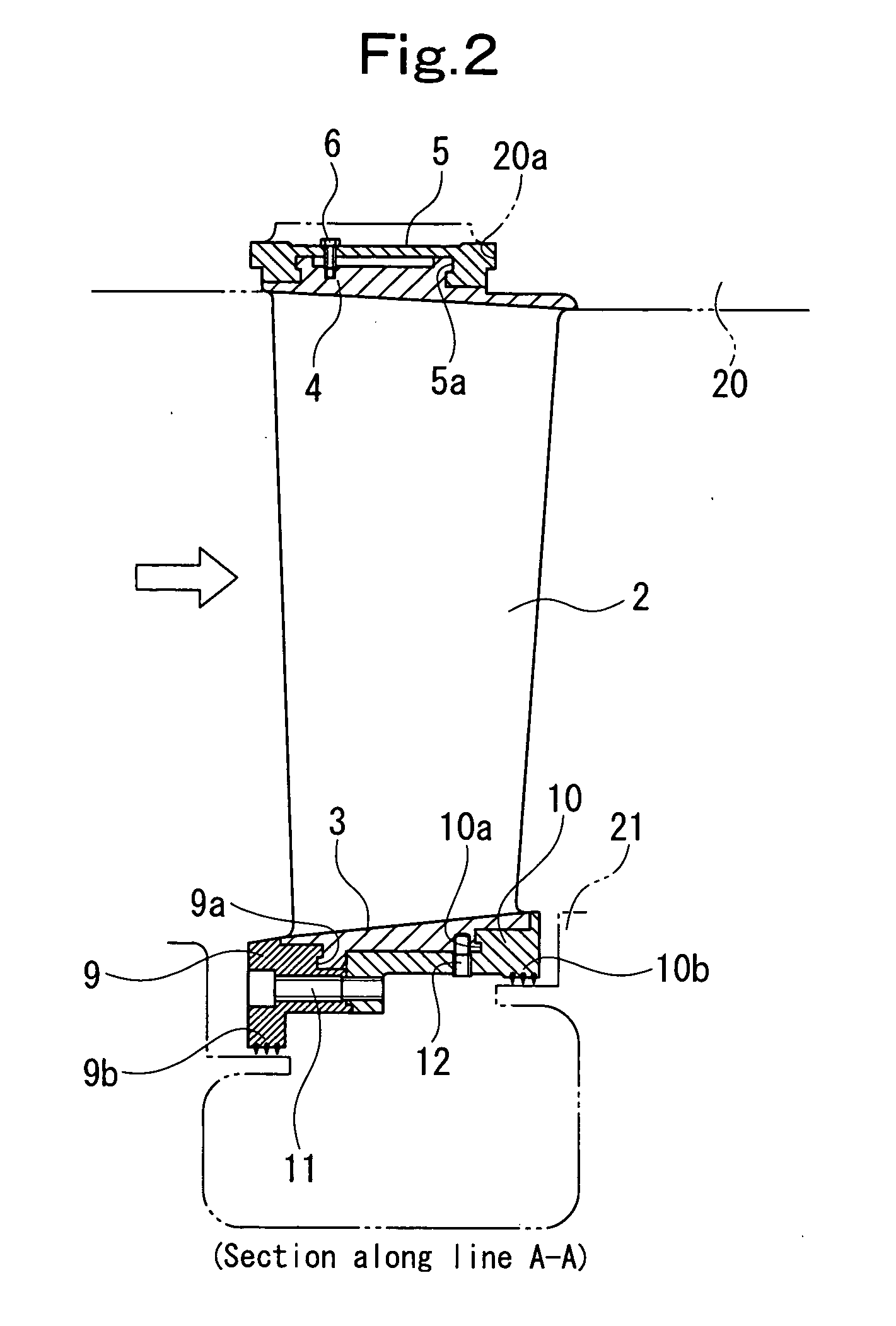
[0029]FIG. 1 is a front view of a compressor stationary blade ring of a gas turbine, showing Embodiment 1 of the present invention. FIG. 2 is a sectional view taken on line A-A in FIG. 1. FIG. 3 is a view taken along line B-B in FIG. 1.

[0030]As shown in FIG. 1, a compressor stationary blade ring 1 of a gas turbine according to the present embodiment is divided into first to fourth units, 1a to 1d, in the circumferential direction. The first unit 1a is equipped with seven stationary blades 2, the second unit 1b is equipped with eight stationary blades 2, the third unit 1c is equipped with seven stationary blades 2, and the fourth unit 1d is equipped with eight stationary blades 2. The first unit 1a and the second unit 1b are built into an upper half of a compressor casing 20 (see FIG. 2), while the third unit 1c and the fourth unit 1d are built into a lower half of the compressor casing 20.

[0031]The structures of the first unit 1a to the fourth unit1d will be described with reference...

embodiment 2

[0042]FIG. 4 is an exploded perspective view of essential parts of the compressor stationary blade ring of the gas turbine, showing Embodiment 2 of the present invention. FIG. 5 is an enlarged sectional view of the essential parts in FIG. 4.

[0043]This is an embodiment in which the outer shroud portion 4 and the spacer 8 in Embodiment 1 are coupled together by a narrow band member 5A (coupling means) fitted into dovetail grooves 4a (the dovetail groove of the spacer 8 is not shown) formed in upper surface regions (on the outer peripheral side) of the outer shroud portion 4 and the spacer 8, and the outer shroud portion 4 and the spacer 8 are directly slidably fitted into the guide groove portion 20a of the compressor casing 20. Other features are the same as those in Embodiment 1.

[0044]According to this embodiment, the advantage is obtained that the band member 5A can be formed compactly, in addition to the same actions and effects as those in Embodiment 1. In the present embodiment ...

embodiment 3

[0045]FIG. 6 is a sectional view of the essential parts of the compressor stationary blade ring of the gas turbine, showing Embodiment 3 of the present invention.

[0046]This is an embodiment in which the outer shroud portions 4 (and spacers 8) in Embodiment 1 are coupled together by a narrow auxiliary band member 7 different from the band member 5 before they are coupled together by the band member 5. Other features are the same as those in Embodiment 1.

[0047]According to this embodiment, in addition to the same actions and effects as those in Embodiment 1, there is the advantage that the stationary blades 2 are not separated from each other even when the band member 5 is detached during a dismounting operation for inspection or the like.


PUM


Abstract

An inner shroud portion and an outer shroud portion dividedly formed per stationary blade are formed integrally with each stationary blade. A plurality of the stationary blades adjacent to each other in a circumferential direction are coupled together by a band member at the outer shroud portions. The inner shroud portions are held between seal holders which are formed as two divided members in the flowing direction of a working fluid, which are fastened by a bolt, and which have a length corresponding to the plurality of the stationary blades. The plurality of stationary blades, the inner and outer shroud portions, the band member, and the seal holders assembled in this manner constitute a unit. A plurality of the units are connected in the circumferential direction to constitute a stationary blade ring of an axial compressor.

Description

BACKGROUND OF THE INVENTION[0001]1. Field of the Invention[0002]This invention relates to a stationary blade ring of an axial compressor, such as a gas turbine compressor, the stationary blade ring being designed to improve reliability and performance of a compressor by achieving built-up stationary blades.[0003]2. Description of the Related Art[0004]FIGS. 7(a) and 7(b) are explanation drawings of a compressor stationary blade ring of a conventional gas turbine, FIG. 7(a) being a sectional view, and FIG. 7(b) a view taken in the direction of an arrow C in FIG. 7(a). In the drawings, the numeral 100 denotes a stationary blade of a compressor, and the numeral 101 denotes an outer shroud for the stationary blade. The outer shroud 101 is built into a compressor casing 102. The numeral 103 denotes an inner shroud. The stationary blade 100 is fixed by fillet welding to the outer shroud 101 and the inner shroud 103 at tenon portions (protrusions) 100a and 100b, respectively. The numerals 1...

Claims


Application Information

Patent Timeline
IPC IPC(8): F01D9/00
CPCF01D5/225F01D9/041F05D2230/60F04D29/542F05B2260/301F01D9/042F01D5/26F01D9/04F01D25/04
Inventor SEKI, NAOYUKIICHIRYU, TAKU
Owner MITSUBISHI POWER LTD
Why Eureka
Try Eureka