Liquid chemical supply system

a technology of liquid chemical supply and liquid chemical, which is applied in the direction of positive displacement liquid engine, pump parameter, piston pump, etc., can solve the problem that liquid chemical may no longer be able to be discharged as intended, and achieve the effect of accurate detection, high degree of accuracy and high degree of accuracy

Inactive Publication Date: 2007-08-02
CKD
View PDF7 Cites 36 Cited by
  • Summary
  • Abstract
  • Description
  • Claims
  • Application Information

AI Technical Summary

Benefits of technology

[0076]As the pump chamber 13 in the liquid chemical pump 10 is sealed and the air pressure is changed by means of the electropneumatic regulator 28, and an air intrusion determination is performed based upon the amount of bellows extension or contraction (the change in bellows length), air intrusion can be accurately detected in the pump chamber 13. The exhaustion of liquid chemical in the liquid chemical tank can also be determined based upon the results of the air intrusion detection. In addition, when an air removal operation is to be performed after air intrusion, it will also be possible to accurately determine whether or not all gas has been discharged. Thus, liquid chemical discharge supply can be ideally performed by means of the liquid chemical pump 10.
[0077]Since the system is constructed to perform feedback control of the movement speed of the diaphragm plate 16 that forms the bellows-type diaphragm 12 during liquid chemical intake or discharge (i.e., constructed to perform feedback control of the amount of operation thereof), the change in volume of the pump chamber 13 can be controlled as intended. In this way, it will be possible to control the liquid chemical intake flow rate or discharge flow rate at an intended flow rate with a high degree of accuracy.
[0078]In the performance of operation amount feedback control, the position detector 36 is an indispensable constituent. In the aforementioned construction in which the detection results of the position detector 36 are employed in order to determine air intrusion inside the pump chamber 13, a

Problems solved by technology

However, if it is not confirmed whether or not the air has been completely removed therefrom before the liquid chemical pu

Method used


Image

  • Liquid chemical supply system
  • Liquid chemical supply system
  • Liquid chemical supply system

Examples


first embodiment

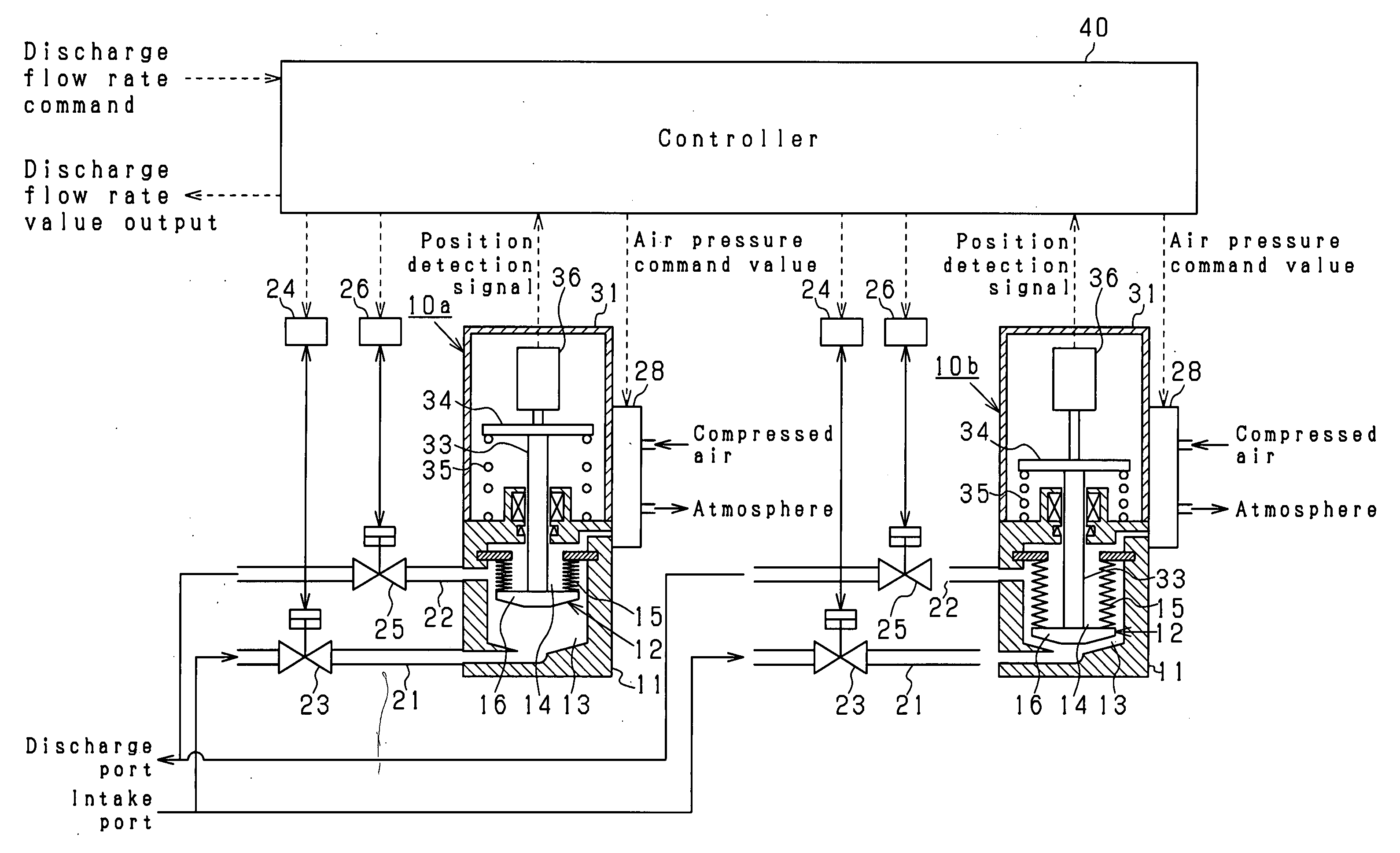
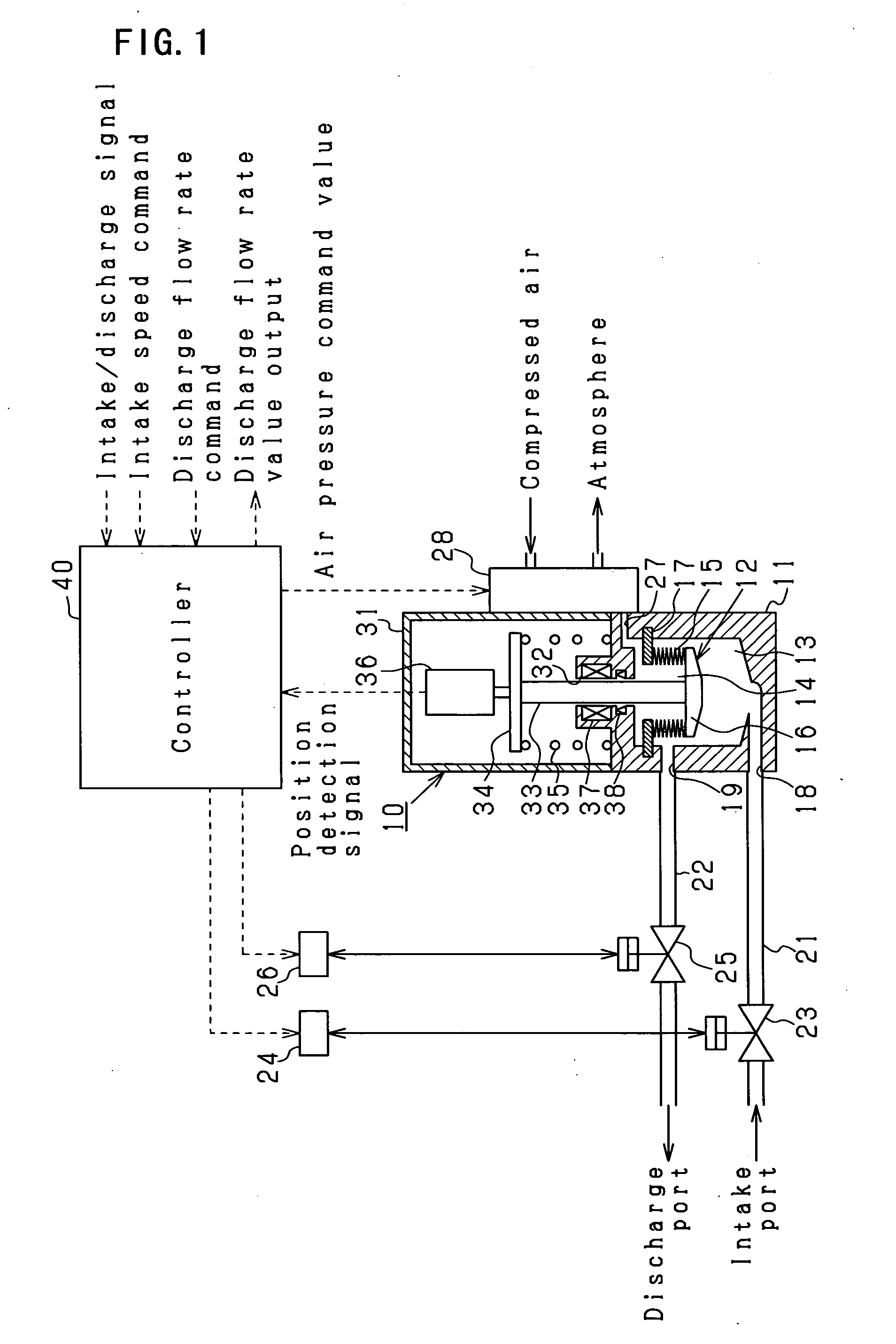
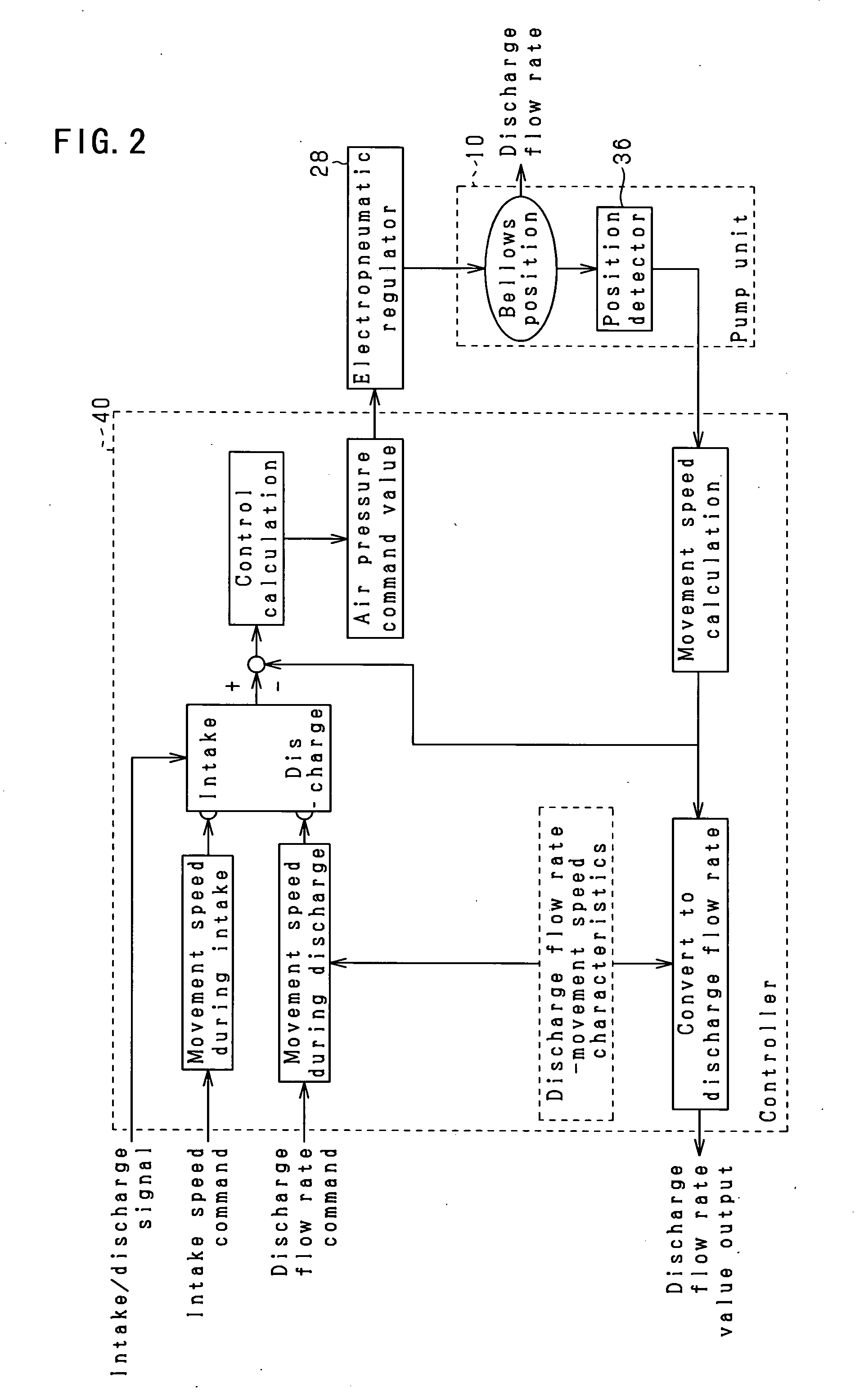
[0039]A first embodiment of the present invention will be described below in accordance with the drawings. The present embodiment is embodied as a liquid chemical supply system which is used in a production line of a semiconductor device or the like. The basic construction of this system will be described based upon FIG. 1.

[0040]The liquid chemical supply system of FIG. 1 comprises a liquid chemical pump 10 for performing the intake and discharge of liquid chemical. A bellows-type diaphragm 12 as a volume variation member is housed inside a pump housing 11 of the liquid chemical pump 10. A pump chamber 13 and a pressure application chamber 14 are separately formed by means of the bellows-type diaphragm 12. The bellows-type diaphragm 12 has a bellows 15 that is compressible in the axial direction, and a diaphragm plate 16 that is attached to one end of the bellows 15 (the lower end in the drawing), and the other end of the bellows 15 (the upper end in the drawing) is fixed to an annu...

second embodiment

[0083]In the aforementioned embodiment, the air pressure was changed by the electropneumatic regulator 28 with the pump chamber 13 sealed in the liquid chemical pump 10, and an air intrusion determination was performed based upon the amount of extension or contraction of the bellows at that time. However, in the second embodiment, the aforementioned method is changed with respect to the air intrusion determination. In other words, in the present embodiment, after first opening the intake valve 23 in order to perform intake, the air pressure will be controlled with the electropneumatic regulator 28, and the bellows type diaphragm 12 will be displaced while resisting the urging force of the compression coil spring 35. Next, the pump chamber 13 will be sealed, and the air pressure control by the electropneumatic regulator 28 will be released in this state. Then, an air intrusion determination will be performed based upon the change in the bellows length at that time.

[0084]A summary of ...


PUM


Abstract

A liquid chemical supply system includes a liquid chemical pump having a pump chamber for supplying a liquid chemical and a volume variation member that will vary the volume of the pump chamber, and will intake or discharge the liquid chemical based upon a change in the volume of the pump chamber in accordance with the volume variation member. The system also comprises an operation means for causing the volume variation member to operate, an operation amount detection means for detecting the operation amount of the volume variation member, a displacement control means for performing displacement control so that the volume variation member will be displaced by the operation means when liquid chemical ports that lead to the pump chamber are in the closed state, and a determination means for determining the presence or absence of gas inside the pump chamber based upon the operation amount detection results from the operation amount detection means during displacement control.

Description

[0001]The present application claims priority based on Japan Patent Application No. 2006-018504 filed on Jan. 27, 2006, and the entire contents of that application is incorporated by reference in this specification.FIELD OF THE INVENTION[0002]The present invention relates to a liquid chemical supply system that employs a liquid chemical pump in order to perform intake and discharge of a liquid chemical, and also relates to a liquid chemical supply system that is suitable for a semiconductor manufacturing device which uses a liquid chemical in order to, for example, apply to a semiconductor.BACKGROUND ART[0003]A liquid chemical pump is provided with a semiconductor manufacturing device in order to apply a predetermined quantity of liquid chemical to a semiconductor wafer. One of the liquid chemical pumps is designed such that a pump chamber in which liquid chemical is stored and a pressure application chamber that introduces compressed air are separated by a separation member such as...

Claims


Application Information

Patent Timeline
IPC IPC(8): F04B43/06F04B11/00
CPCF04B7/02F04B43/0081F04B2201/0201F04B43/113F04B49/065F04B43/084B05C11/1002H01L21/6715
Inventor KATO, TAKASHI
Owner CKD
Why Eureka
Try Eureka