
Manual driver for implant drills and method of dental implantation

a technology of implant drills and driver devices, which is applied in the field of manual driver devices for implant drills and dental implantation, can solve the problems of reducing the diameter of the implant hole, reducing the risk of bone cracking, so as to improve the diameter and prevent bleeding

Active Publication Date: 2007-08-02
MURIAS GERMAN L
View PDF9 Cites 11 Cited by
  • Summary
  • Abstract
  • Description
  • Claims
  • Application Information

AI Technical Summary

Benefits of technology

[0009]In a further aspect, the present invention is directed to a manual preparation method for dental implantation. In one embodiment, the method comprises the steps of providing a manual driver comprising a handle and a chuck configured to receive and lock an implant drill therein; securing a shaft of a first implant drill into the chuck of the manual driver; manually driving the first implant drill at a selected location to create an initial bore by turning the driver clockwise and counter clockwise until the first implant drill reaching a desired depth; taking a x-ray image of the initial bore to confirm proper angulation of the initial bore; manually driving one or more implant drills that has an increased diameter from the first implant drill using the manual driver to expand the initial bore by turning the driver clockwise and counter clockwise until obtaining a final bore having a desired diameter; removing the implant drills, and collecting bone tissue on threads of each of the implant drills into a sterilized container; placing collected bone tissue back into the final bore; and placing the dental implant into the final bore that is filled with the collected bone tissue. Preferably, after the first drilling, the first implant drill is remained in the initial bore for taking the x-ray image, and to prevent bleeding.

Problems solved by technology

Since motor-driven drilling causes vibrations, at the area where bone is very thin it tends to cause cracking of the bone and renders implantation impossible.
Furthermore, motor-driven drilling provides one directional drilling, i.e., clockwise, which generates more pressure on the surrounding bone, hence, this also poses a higher risk of bone cracking, as well as causes more trauma to the patient.
Consequently, in some areas or situations implantations have been considered not permissible because of the risks associated with the drilling.
Furthermore, because of the high speed and the vibration of motor-driven drilling, it requires substantial skills and experiences in proper control of the angulation of drilling.
Additionally, using motor-driven drilling, the dentists have a limited tactile sensation about the surrounding bone structures in the process of drilling.
Moreover, motor-driven drilling generates heat, therefore, water cooling of the drill and the bore is required.
This interrupts the process and can be dangerous during drilling.
Moreover, the cooling water also causes a further disturbance of the wound.
Such a process can cause dehydration of the bone tissue, which affects the quality of the collected bone tissue, and bone regeneration surrounding the implant.

Method used


Image

  • Manual driver for implant drills and method of dental implantation
  • Manual driver for implant drills and method of dental implantation
  • Manual driver for implant drills and method of dental implantation

Examples


Embodiment Construction

and Claims appended herewith.

BRIEF DESCRIPTION OF THE DRAWINGS

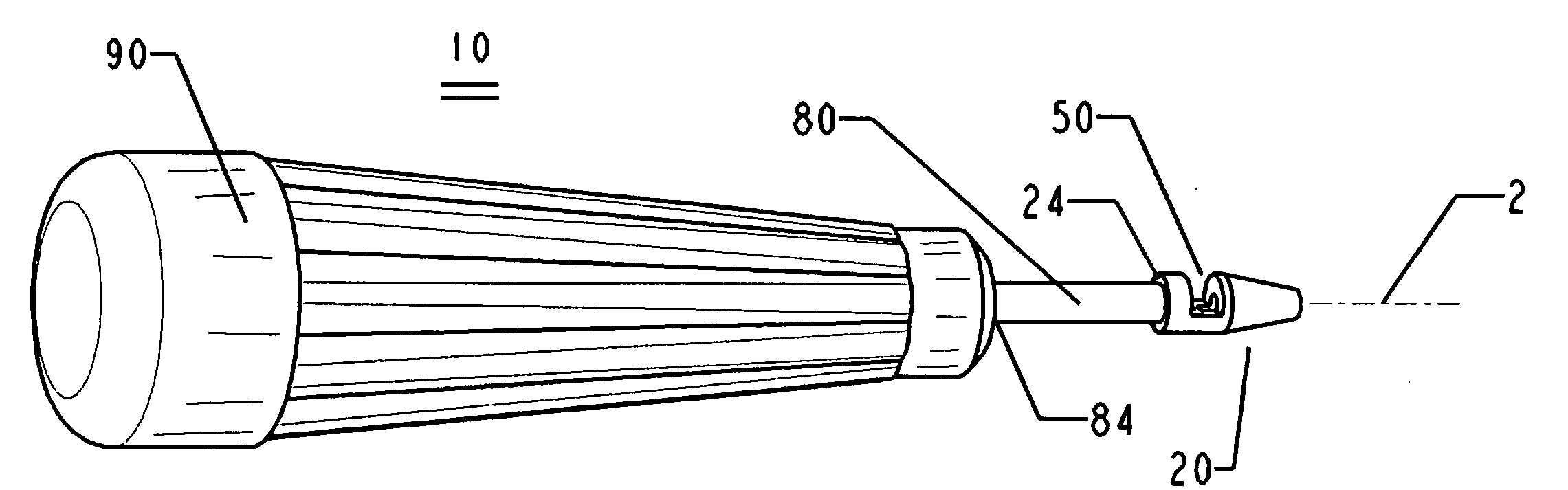
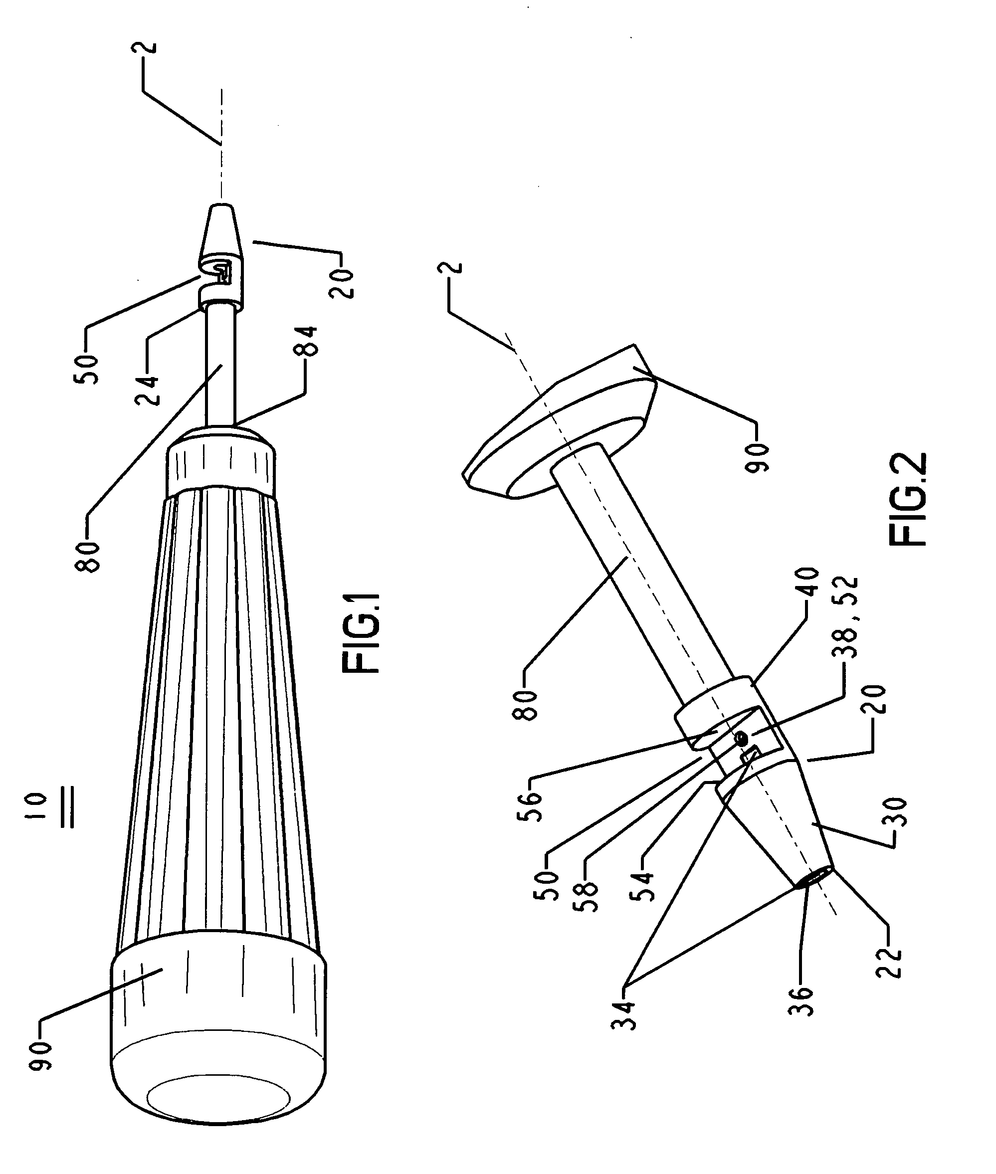
[0012]FIG. 1 is a perspective view of the manual driver.

[0013]FIG. 2 is an enlarged perspective view of the chuck and the extension shank of the instant manual driver.

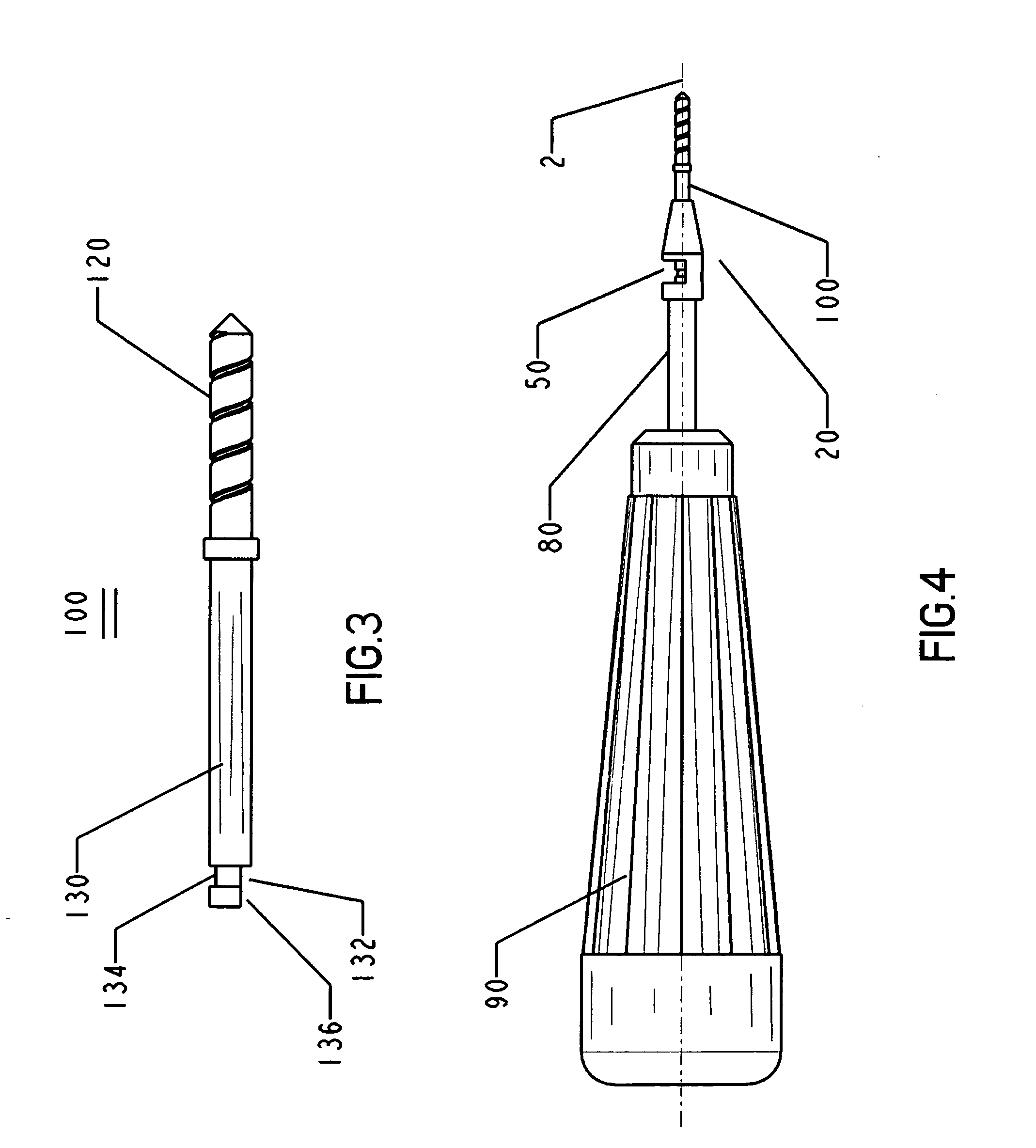
[0014]FIG. 3 is an example of a commercial available implant drill that may be used with the manual driver of the present invention.

[0015]FIG. 4 is a side view of the manual driver, including an implant drill secured therein.

[0016]FIG. 4A is a fragmentary axial cross-sectional view along the longitudinal axis of said manual driver.

[0017]FIG. 4B is a bottom view of the chuck shown in FIG. 4.

[0018]FIG. 5 is a fragmentary axial cross-sectional view along the longitudinal axis of said manual driver, showing a variation of the transverse bore and an Allen head screw.

[0019]FIG. 6 is a fragmentary axial cross-sectional view along the longitudinal axis of said manual driver, showing the enlarged screw head being disposed outside of the transverse bore.

[0020]It is no...


PUM


Abstract

A manual driver for a dental implant drill or other dental implant tools and the method of use for preparing for dental implantation are provided. The manual driver includes a handle, an extension shank and a chuck having an axial channel configured to receive and interlock an implant drill, and a fastening screw transverse to the axial channel. The method of manual preparation for dental implantation using the manual driver has a high precision, and reduces the risk of bone cracking caused by vibration of motor-driven drilling. The manual drilling method provides better tactile sensation and drilling control to the dentist. Further, the method avoids drilling irrigation, allows collection of virgin bone tissue from the drills, and reintroduces the collected bone tissue in the receiving bore to promote bone regeneration after the implantation.

Description

CROSS REFERENCE TO RELATED APPLICATION[0001]This application claims the benefit under 35 USC 119 (e) of the provisional patent application Ser. No. 60 / 762,730, filed on Jan. 27, 2006, which is hereby incorporated by reference in its entirety.FIELD OF THE INVENTION[0002]The present invention relates to a manual driver configured to receive and drive an implant drill or other dental implant tools, and the methods of manual preparation for dental implantation using the manual driver.BACKGROUND OF THE INVENTION[0003]Currently, in all dental implantation procedures drilling is performed using motor-driven drilling. Motor-driven drilling has certain advantages, such as fast and less labor demanding, however, it also has various drawbacks. For example, in the process of preparing dental implantation, drilling is frequently made on a location which has very thin bones. Since motor-driven drilling causes vibrations, at the area where bone is very thin it tends to cause cracking of the bone a...

Claims


Application Information

Patent Timeline
Patent Type & Authority Applications(United States)
IPC IPC(8): A61C3/00
CPCA61C8/0089
Inventor MURIAS, GERMAN L.
Owner MURIAS GERMAN L
Learn More