Variable flywheel mechanism and flywheel apparatus

a technology of rotating flywheel and rotating shaft, which is applied in the direction of flywheels, toothed gearings, gearings, etc., can solve the problems of fuel efficiency, slow response during acceleration, and irregular force transmitted to the crankshaft, so as to improve the capacity for acceleration and deceleration, the effect of easy reduction and lightening of the weigh

Inactive Publication Date: 2007-08-02
HONDA MOTOR CO LTD
View PDF9 Cites 20 Cited by
  • Summary
  • Abstract
  • Description
  • Claims
  • Application Information

AI Technical Summary

Benefits of technology

[0021]Part of the variable flywheel mechanism is configured from the pivotable arms and the weights. The pivotable arms and weights are smaller and lighter in weight in comparison with the conventional circular plate-shaped flywheel shown in FIG. 8. The two flywheels (first flywheel and second flywheel) shown in FIG. 8 are unneces

Problems solved by technology

The explosive power of an engine, for example, is generated in sequence in cylinders, but there may be irregularities in the force transmitted to the crankshaft used as the output shaft of the engine.
Therefore, when the crankshaft is rotating at high speeds, the presence of a flywheel apparatus has an adverse effect on fuel efficiency and results in a slower response during acceleration.
First, one problem is that the moment of inertia has a narrow variability range. Generally, a greater variability range in the moment of inertia allows for greater variability control. It is advantageous to bring the mass (the flywheel mass, a weight) near the rotational center in order to bring down the lowe

Method used


Image

  • Variable flywheel mechanism and flywheel apparatus
  • Variable flywheel mechanism and flywheel apparatus
  • Variable flywheel mechanism and flywheel apparatus

Examples


Embodiment Construction

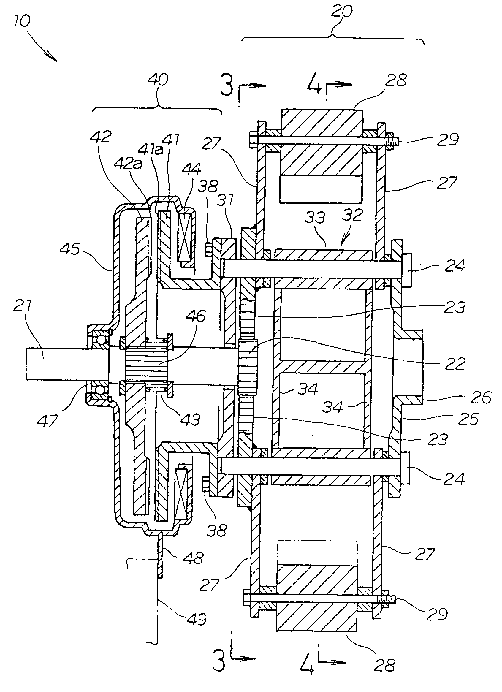
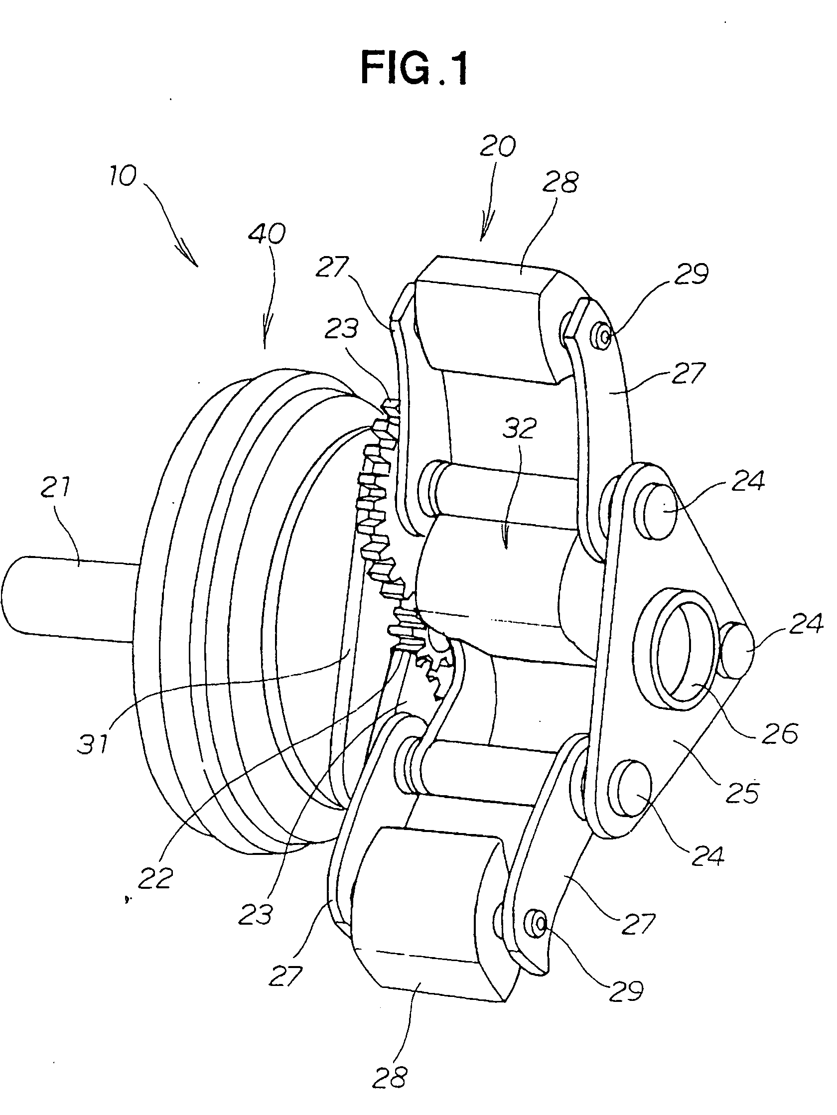
[0037]A flywheel apparatus 10 shown in FIG. 1 is comprised of a variable flywheel mechanism 20 and a switching clutch mechanism 40.

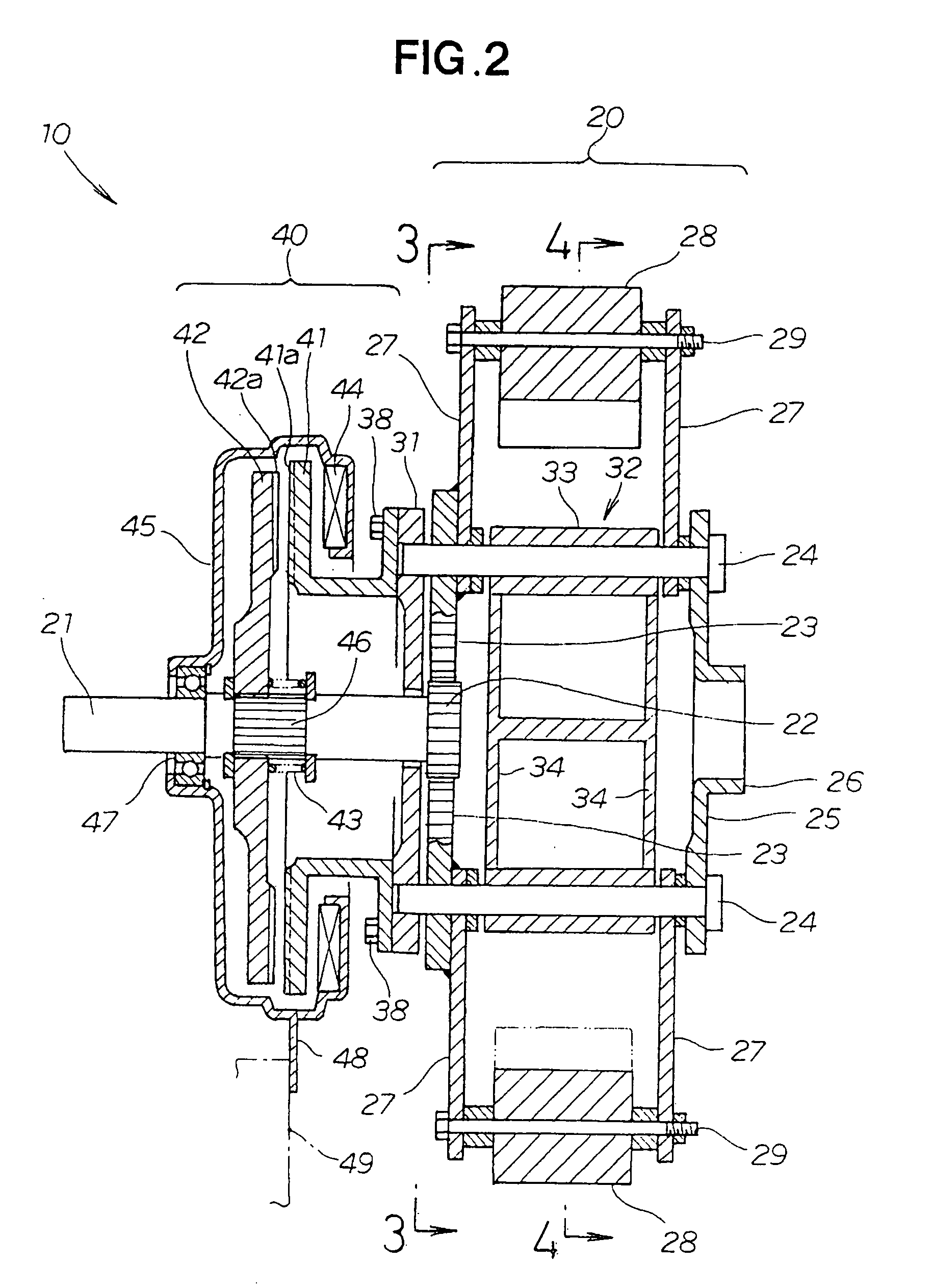
[0038]The variable flywheel mechanism 20 shown in FIG. 2 has a sun gear 22 connected to an output shaft 21 of an engine, multiple planetary gears 23 that mesh with the sun gear 22, multiple carrier shafts 24 for rotatably supporting the planetary gears 23, a carrier assembly 25 for linking the distal ends of the carrier shafts 24 together, a flywheel output shaft 26 that extends from the carrier assembly 25, pivotable arms 27 that are swingably mounted on the carrier shafts 24 and that are swung by the planetary gears 23, and weights 28 that are mounted on these pivotable arms 27.

[0039]The weights 28 are integrally mounted on the pivotable arms 27, 27 by means of long bolts 29 spanning the distance between the left and right pivotable arms 27, 27. With this structure, the weights 28 can be replaced. If the weights 28 do not need to be replaced, the weigh...


PUM


Abstract

A variable flywheel mechanism is capable of varying the moment of inertia is disclosed. The wheel mechanism includes a sun gear, planetary gears, pivotable arms swung by the planetary gears, and weights mounted on the pivotable arms. The positions of the weights are controlled by rotation of the sun gear.

Description

FIELD OF THE INVENTION[0001]The present invention relates to a variable flywheel mechanism and a flywheel apparatus wherein the moment of inertia can be varied.BACKGROUND OF THE INVENTION[0002]The explosive power of an engine, for example, is generated in sequence in cylinders, but there may be irregularities in the force transmitted to the crankshaft used as the output shaft of the engine. The irregularities appear as torque fluctuations or fluctuations in the rotational speed of the crankshaft. It is known that if a heavy object known as a flywheel is attached to the crankshaft, these irregularities can be corrected with the moment of inertia of the heavy object.[0003]Fluctuations in the rotational speed or torque (hereinafter referred to as fluctuations in rotational speed) of the crankshaft are particularly severe when the crankshaft is rotating at a low speed, such as is the case during idling (hereinafter referred to as low-speed rotation). Installing a flywheel apparatus ther...

Claims


Application Information

Patent Timeline
IPC IPC(8): F16H57/08
CPCF16F15/31
Inventor KIMURA, YASUNARITSUBOI, TAKAOENDOH, TSUNEO
Owner HONDA MOTOR CO LTD
Why Eureka
Try Eureka