Magnetic spinal implant device

a magnetic spinal and implant technology, applied in the field of magnetic spinal implants, can solve the problems of not providing any “cushion” or “shock absorption” to relieve axial pain, affecting the stability of spinal bones that the implants are attached to, and affecting the patient's recovery, etc., and achieves the effect of rapid turning on and off or manipulating

a magnetic spinal and implant technology, applied in the field of magnetic spinal implants, can solve the problems of not providing any “cushion” or “shock absorption” to relieve axial pain, affecting the stability of spinal bones that the implants are attached to, and affecting the patient's recovery, etc., and achieves the effect of rapid turning on and off or manipulating

US20070179493A1Inactive Publication Date: 2007-08-02KIM RICHARD C

Image

  • Magnetic spinal implant device
  • Magnetic spinal implant device
  • Magnetic spinal implant device

Examples


Embodiment Construction

[0042]The invention is described in detail below with reference to the figures, wherein like elements are referenced with like numerals throughout. It should be understood that the figures are not necessarily drawn to scale. Rather, they are intended to show certain features and elements of various exemplary embodiments of the invention.

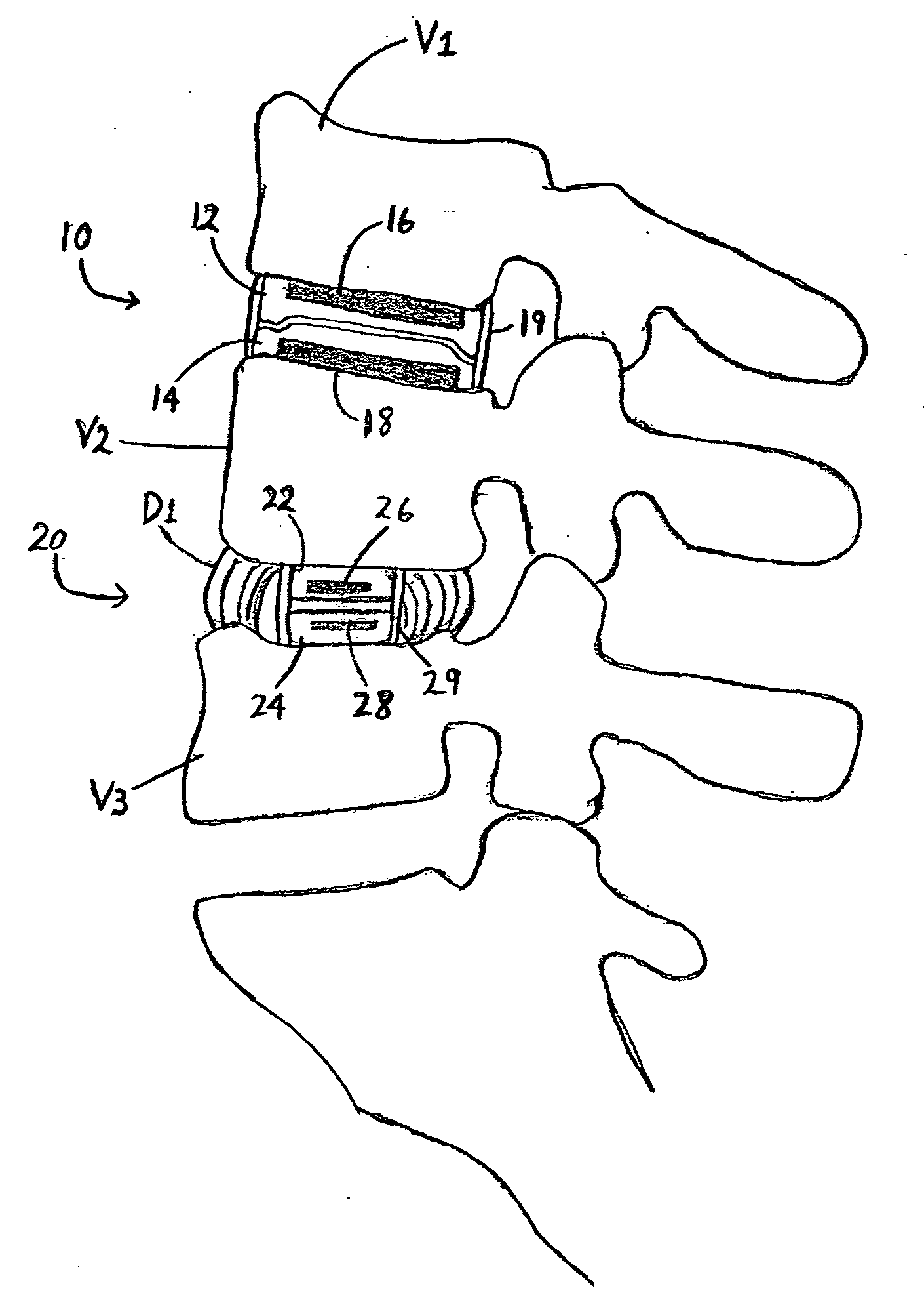
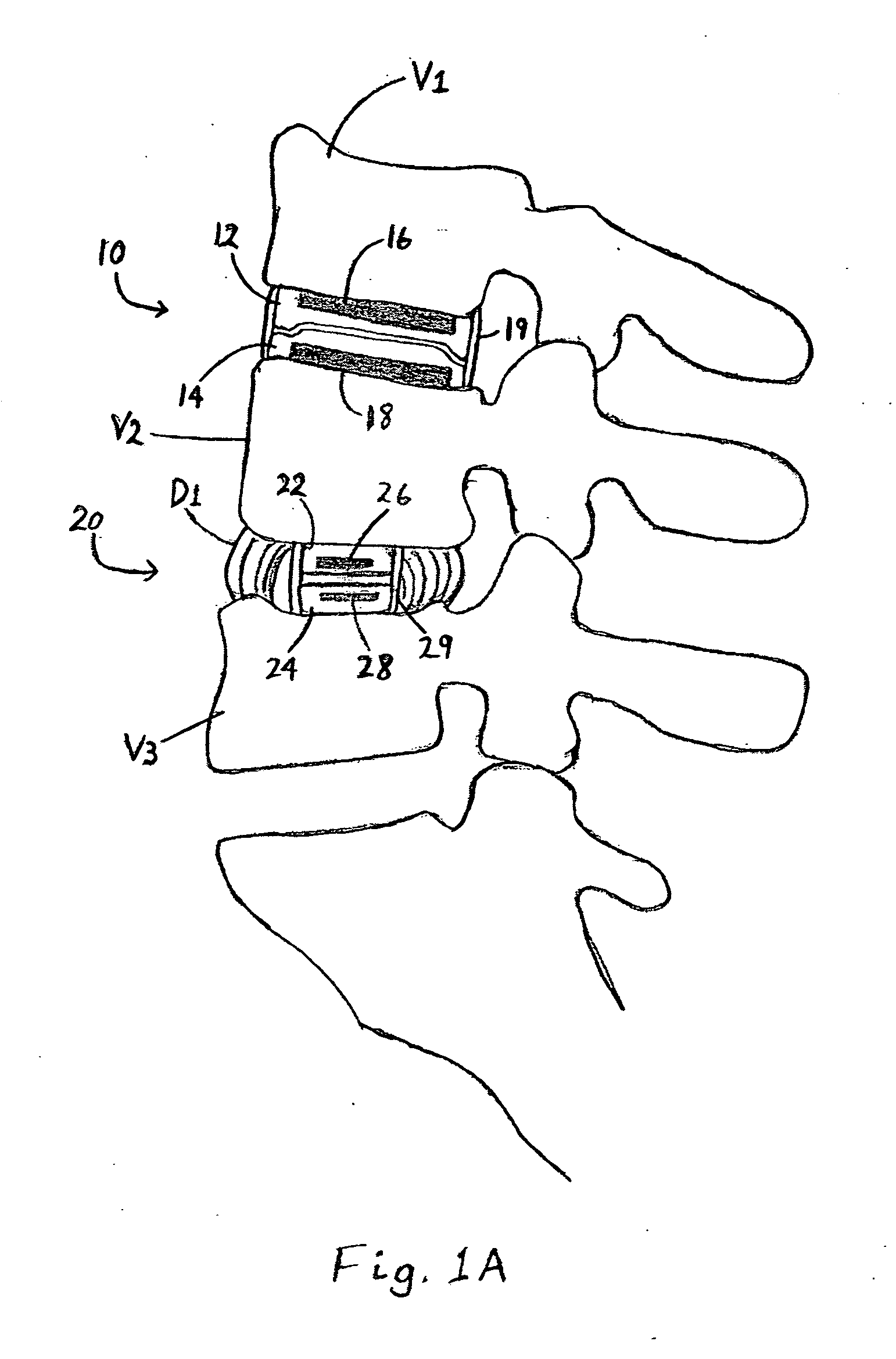
[0043]FIG. 1A illustrates a cross-sectional side view of a patient's spine having two magnetic intervertebral disk implants 10 and 20 implanted therein. The implants 10 and 20 are illustrated together for purposes of discussion only and need not be used together in actual applications. The magnetic implant 10 is designed to replace the entire disk between vertebras V1 ad V2 and includes a first piece 12 configured to be secured to first vertebral body V1 and a second piece 14 configured to be secured to second vertebral body V2. Each of the first and second pieces 12 and 14 can be secured to their respective vertebral bodies using known means and tec...


PUM


Abstract

A magnetic spinal implant device is disclosed. In one embodiment, the device includes: a first piece configured to be implanted into a patient and coupled to the patient's spine, wherein the first piece includes a recessed portion; a first magnet coupled to the first piece; a second piece configured to be implanted into the patient and juxtaposed with the first piece, wherein the second piece includes a base portion surrounding a raised portion, wherein the raised portion is configured to be at least partially received within the recessed portion of the first piece so as to facilitate alignment of the first and second pieces; and a second magnet coupled to the second piece, wherein the first magnet exerts a desired magnetic force on the second magnet.

Description

RELATED APPLICATIONS[0001]This application claims priority under 35 U.S.C. § 119(e) to U.S. provisional application Ser. No. 60 / 759,094, entitled “Magnetic Spinal Implants,” filed on Jan. 13, 2006, the entirety of which is incorporated by reference herein.BACKGROUND OF THE INVENTION[0002]1. Field of the Invention[0003]The present invention relates to spinal implants and, more particularly, to spinal implant devices utilizing magnetic fields to provide magnetic attraction and / or repelling forces between two or more vertebral bodies or spinal structures.[0004]2. Description of the Related Art[0005]Various types of spinal implant devices are well known in the art. For example, implants are commonly used to replace all or a portion of damaged vertebral bodies and intervertebral disks of the human spine. One disadvantage of conventional spinal implant devices, however, is that they are typically made of a biocompatible metal or other similar material which is hard and rigid and, therefor...

Claims


Application Information

Patent Timeline
02 Aug 2007
Publication
US20070179493A1
IPC
A61B18/04
CPC
A61B17/7008; A61F2310/00179; A61B17/7062; A61F2/442; A61F2/4465; A61F2002/2821; A61F2002/30079; A61F2002/30133
Inventors
KIM, RICHARD C.