
Suture retention device

a technology of suture and retaining device, which is applied in the field of surgical equipment, can solve the problems of affecting the deployment or readjustment of peripheral devices, affecting the effect of peripheral devices, and consuming time, and achieves the effect of reducing the likelihood of induction

Inactive Publication Date: 2007-08-02
CORONEO
View PDF30 Cites 24 Cited by
  • Summary
  • Abstract
  • Description
  • Claims
  • Application Information

AI Technical Summary

Benefits of technology

[0036] In some surgical interventions, the foregoing features contribute to attempt to position and orient the beating heart through retraction of the incised pericardium tissue during beating heart CABG, while tending to minimize the likelihood of inducing physiologically adverse effects such as hemodynamic instability, arrhythmia, or a precipitous drop in arterial pressure.

Problems solved by technology

a) be time consuming, since securing of the retraction load through the manual tying of the suture line lengths is a multi-step threading and knotting procedure;
b) be cumbersome due to poor access during the manual tie down of the suture line lengths, especially in surgical interventions when the surgical window is small;
d) compromise the ergonomics of and the surgeon's access into the surgical window, especially when a surgical clamp is used to secure the two lengths of the suture line to the perimeter of the surgical window or to a portion of the surgical retractor used to create the surgical window, all the more when multiple suture lines need to be secured to achieve the desired organ or body tissue retraction;
e) hinder or restrict the readjustment of the surgical window opening through the opening or closing of the surgical retractor, if the lengths of the suture line are tied to the rack bar of the surgical retractor, or hinder the deployment or readjustment of peripheral surgical devices that are mounted or need to be mounted on the spreader arms of the retractor.
Generally, adjustment of the desired tensile retraction by cutting an existing suture line and repiercing a new suture line is not desirable.
First, the process of placing a suture requires considerable manual dexterity, at times requiring the help of an assistant.
The process is therefore tedious and time consuming.
Second, a repiercing of the internal body tissue or body organ with a subsequent suture tends to increase the likelihood of inducing tissue trauma or tissue tearing which may have to be surgically repaired.
This tissue retraction with suture tends to generally be more difficult due to the smaller access through a laparoscopic entry relative to the larger surgical access window obtained through the traditional retracted incision entry.
One of the challenges in performing beating heart CABG surgery lies in positioning and orienting the beating heart in order to obtain access to the inferior and posterior artery beds, while tending to minimize physiologically undesirable effects such as hemodynamic instability, arrhythmia, or a precipitous drop in arterial pressure, that may occur as a result of such manipulations.

Method used


Image

  • Suture retention device
  • Suture retention device
  • Suture retention device

Examples


first embodiment

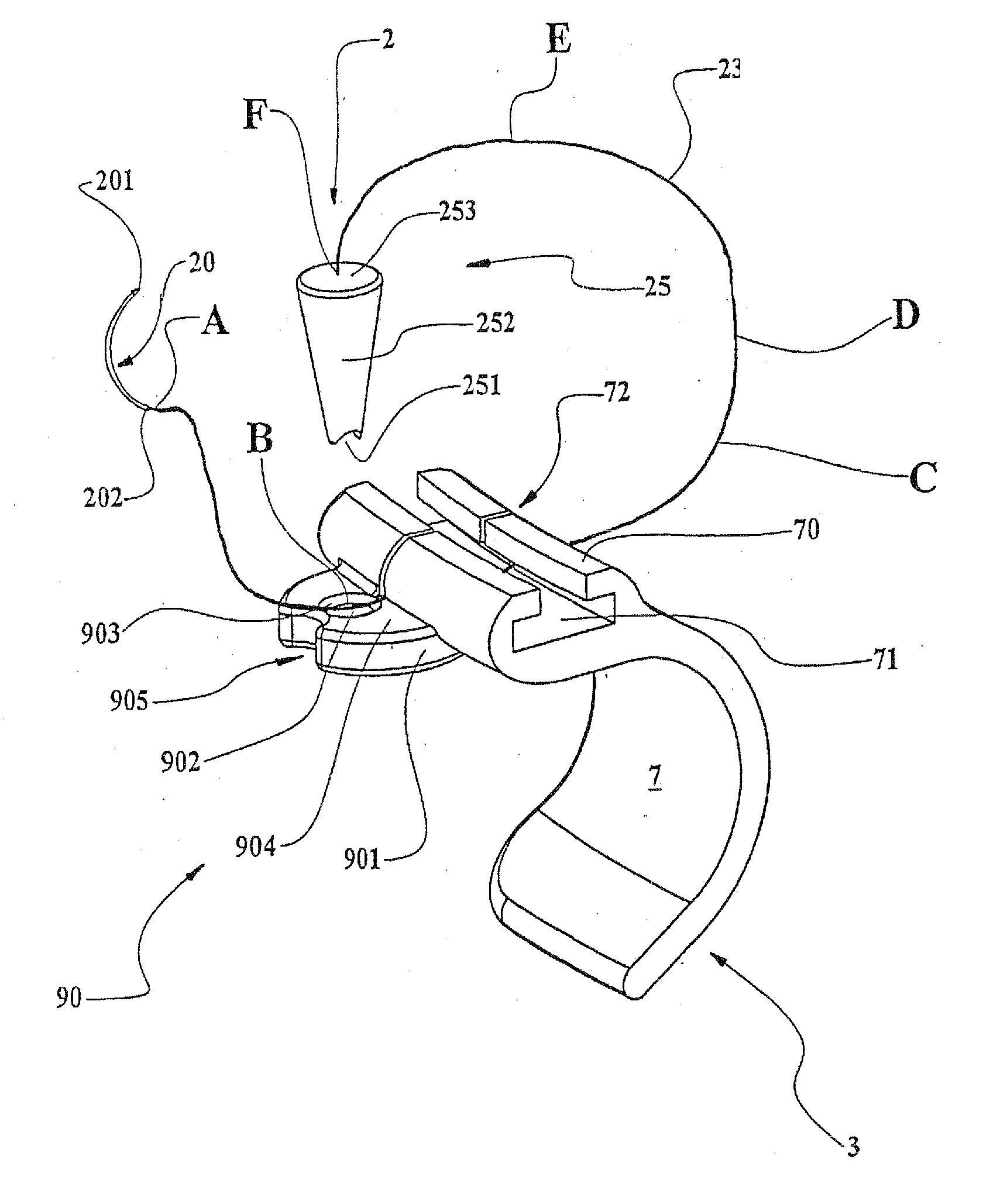
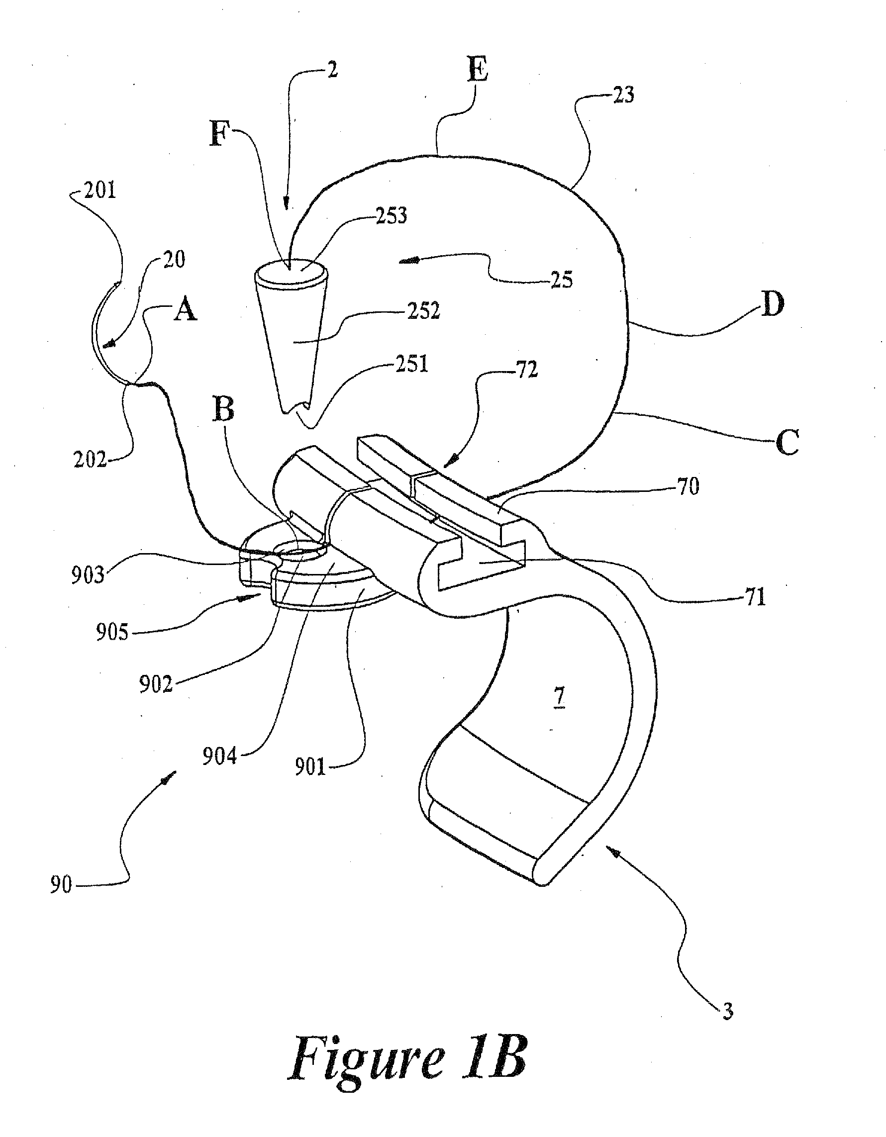
[0064] In this first embodiment, as further illustrated in FIGS. 1B-1D, the anchoring port 90 is illustrated as being integral with the retractor arms 3, such as a cast boss, a brazed-on boss or a welded-on boss. Alternatively, the anchoring port 90 may also be a separate component that is mechanically fastened to the retractor arm 3 (or 4) by a variety of conventional fastening methods, such as bolting or riveting, in a manner that renders it fixed relative to the sternum retractor arm 3 (or 4) on which it is assembled, at least for the duration of the surgical intervention for which tissue retraction is performed. The anchoring port 90 in this embodiment is a substantially cantilevered fitting 901, disposed laterally outwards from the arcuate curvature of retractor arm 3 or 4, its top face 904 preferably having a substantially horizontal orientation when sternum retractor 1 is deployed in the patient. An aperture 902, preferably a through hole, is configured in the center of fitti...

second embodiment

[0092]FIG. 5B illustrates a fully engaged tissue retractor 12 within wedge shaped aperture 914, according to a first preferred method of deployment. As previously explained, the anchoring plug 34 may be manufactured in a material or design that makes it at least partially malleable or partially elastic to tend to improve its conformity to cooperating faces 911 and its compliance around the engaged suture line that it will pinch against faces 911. In broad terms, this preferred method deployment for this second embodiment according to the present invention, consists of:

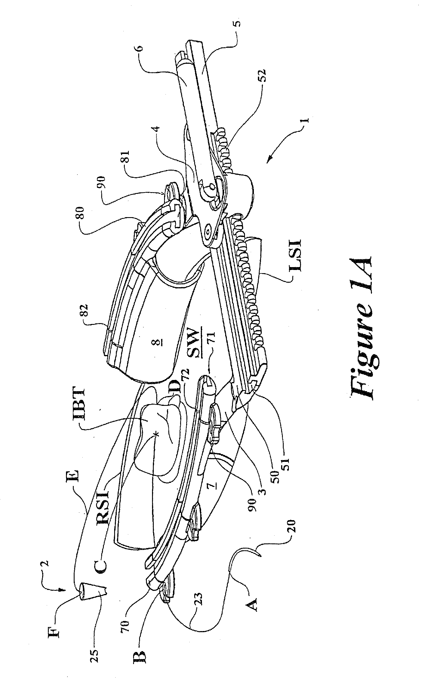
[0093] a) piercing the internal body tissue IBT with needle 20 and threading a length AC of suture line 23 through said internal body tissue IBT;

[0094] b) retracting pierced internal body tissue IBT by simultaneously pulling on both lengths AC and DF of suture line 23;

[0095] c) selecting the most convenient anchoring port 91 from the plurality disposed around sternum retractor 1, estimating the required location of a...

third embodiment

[0111] In broad terms, the method of deployment for this third embodiment according to the present invention, consists of:

[0112] a) piercing the internal body tissue IBT with needle 20 and threading a length AC of suture line 23 through said internal body tissue IBT;

[0113] b) simultaneously inserting both lengths AC and DF of suture line 23 firstly in slit-like channel 72 and secondly in between pinch roller 934 and traction roller 93;

[0114] c) grasping both lengths AC and DF of suture line 23, in the vicinity of point A and point F, and retracting pierced internal body tissue IBT by pulling simultaneously both said lengths longitudinally outward through slit-like channel 72 while all the time maintaining suture-line lengths in contact with pinch roller 934 by laterally loading said suture lines against said pinch roller during the said pulling action;

[0115] d) once the desired internal body tissue IBT retraction or internal body tissue IBT displacement is obtained, displace the ...


PUM


Abstract

A tissue retractor for displacing body tissue during surgery includes a tissue piercing member such as a surgical needle, a wire-like filament such as a suture line affixed to the surgical needle, a fixed element such as an anchoring port being associated with a stable surgical platform such as a sternum retractor and a movable element such as an anchoring plug cooperating with anchoring port to engage a portion of suture line after the suture line is threaded through the body tissue with the surgical needle and after the suture wire is tensioned to effect a predetermined displacement of the body tissue. The predetermined displacement of body tissue is maintained by retention of the engaged portion of suture line by the fixed anchoring port and the movable anchoring plug.

Description

[0001] This application is a continuation application of prior U.S. patent application Ser. No. 10 / 365,481, filed on Feb. 13, 2003 (pending) which is a continuation of U.S. patent application Ser. No. 09 / 762,437, filed on Apr. 10, 2001 (now U.S. Pat. No. 6,547,725) which is a U.S. National Stage of International Application No. PCT / CA99 / 00740, filed on Aug. 10, 1999 (expired), which claims the priority of Canadian Patent Application No. 2242245, filed Aug. 10, 1998, the disclosures of which are incorporated by reference herein.FIELD OF THE INVENTION [0002] The present invention relates to the field of surgical apparatus and more specifically, to a suture and associated anchoring mechanism for applying tissue retraction during surgery. BACKGROUND OF THE INVENTION [0003] Generally, surgery requires an incision through a patient's skin, underlying muscle and tissue to expose the underlying body organ or anatomical tissue which is in need of the particular surgical intervention. In cert...

Claims


Application Information

Patent Timeline
Patent Type & Authority Applications(United States)
IPC IPC(8): A61B17/04A61B17/02A61B17/06
CPCA61B17/0206A61B17/0293A61B17/0487A61B2017/06052A61B2017/0243A61B2017/045A61B2017/0496A61B17/06061
Inventor PAOLITTO, ANTHONYVALENTINI, VALERIOCARTIER, RAYMOND
Owner CORONEO
Learn More