Electric Rotating Machine and Stator for the Same

a stator and rotating machine technology, applied in the direction of windings, dynamo-electric components, magnetic circuit shapes/forms/construction, etc., can solve the problems of increasing the space factor of the windings embedded in the slots, gaps are formed, and the stator core cannot be formed in a satisfactory manner, so as to achieve efficient assembly

Inactive Publication Date: 2007-08-09
HITACHI LTD
View PDF4 Cites 40 Cited by
  • Summary
  • Abstract
  • Description
  • Claims
  • Application Information

AI Technical Summary

Benefits of technology

[0015] The present invention is intended to solve those problems and it is therefore an object of the present invention to provide a stator for an electric rotating machine, capable of being efficiently assembled, and provided with windings less subject to short circuit and mounted on a stator core in a satisfactorily insulated state.

Problems solved by technology

Although the space factor of the windings embedded in the slots increases remarkably, the stator core cannot be formed in a satisfactory roundness by rolling the flat stator core after embedding the windings in the slots, and gaps are formed in the joint of the opposite sides of the flat stator core.
Consequently, the stator core causes problems including the enhancement of magnetic noise and the reduction of output.
Defective insulation of the windings embedded in the slots occurs due to damaging insulating paper and the insulating coatings of the wires of the windings embedded in the slots by welding heat applied thereto in welding the joint in the cylindrical stator core.
Thus, the automotive alternator requires troublesome assembling work and the insulation of the conductors is liable to be damaged.
The joined parts are often melted and short-circuited during welding, and the automotive alternator is difficult to mass-produce.
Ends of the coils are joined in a plurality of joints, the joints are liable to be short-circuited and thereby the coils are often short-circuited.
Since the plurality of conductor segments are fitted in the slots of the stator core, and the ends of the conductor segments are joined together by welding or the like, troublesome work is needed for positioning the plurality of ends.
If the insulating films coating the joining ends of the conductor segments are removed incompletely, organic gases are produced during welding and deteriorate the quality of the joints.
Thus, additional work is needed for removing the insulating films.
When ends of the conductor segments are melted for welding, the joints are often short-circuited, reducing the quality of mass-produced stators.
Thus, the stator core causes problems including the enhancement of magnetic noise, the reduction of output and the defective insulation of the windings.
Although the space factor of the windings increases remarkably, the stator core cannot be formed in a satisfactory roundness by rolling the flat stator core after embedment of the windings in the slots, and gaps are formed in the joint of the opposite sides of the flat stator core.
Consequently, the stator core causes problems including the enhancement of magnetic noise and the reduction of output.
Defective insulation of the windings embedded in the slots occurs due to damaging insulating paper and the insulating coatings of the wires of the windings embedded in the slots by welding heat applied thereto in welding the joint in the cylindrical stator core.

Method used


Image

  • Electric Rotating Machine and Stator for the Same
  • Electric Rotating Machine and Stator for the Same
  • Electric Rotating Machine and Stator for the Same

Examples


first embodiment

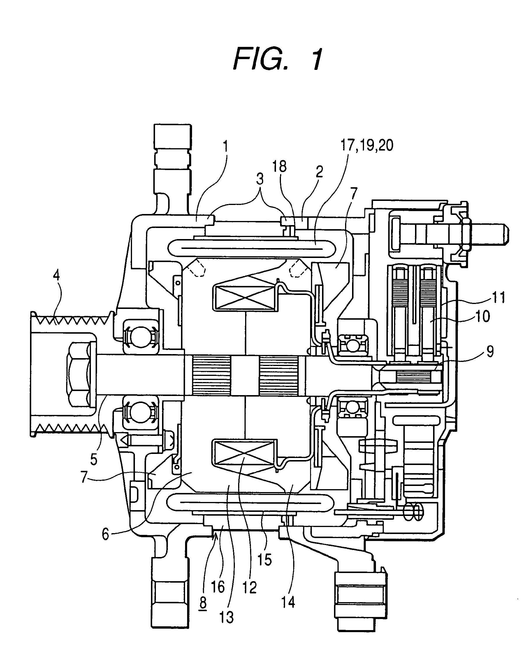
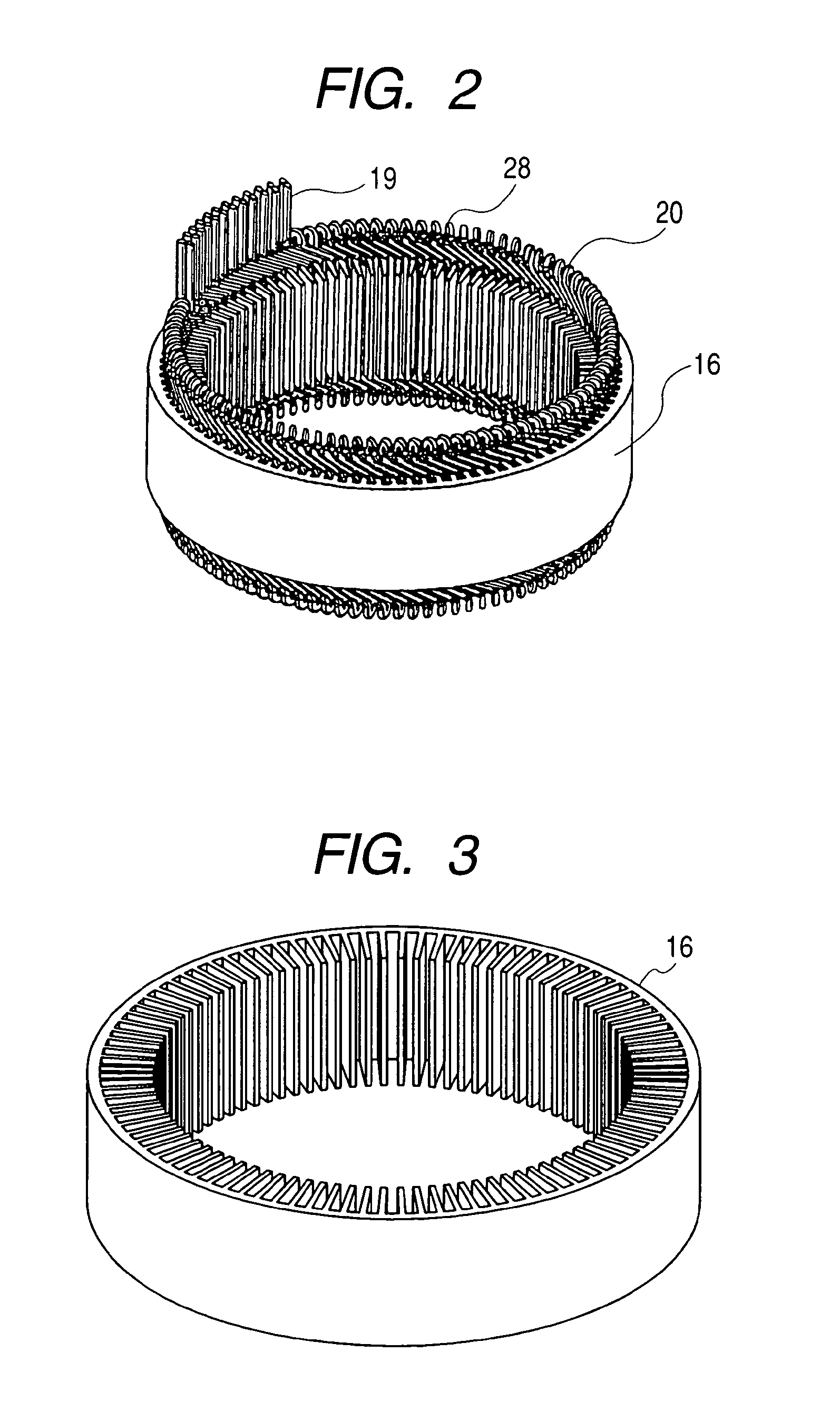
[0032]FIG. 1 is a sectional view of an automotive alternator in a first embodiment according to the present invention, FIG. 2 is a perspective view of a stator included in the automotive alternator shown in FIG. 1, and FIG. 3 is a perspective view of a stator core shown in FIG. 1.

[0033] The alternator includes a case 3 having an aluminum front bracket 1 and an aluminum rear bracket 2, a shaft 5 extended in the case 3 and having one end part on which a pulley 4 is fixedly mounted, a Randall type rotor 6 fixed to the shaft 5, fans 7 attached to the opposite end surfaces of the rotor 6, a stator 8 fixed to the inside surface of the case 3, a slip ring fixed to the other end part of the shaft 5 to supply currents to the rotor 6, a pair of brushes 10 in sliding contact with the slip ring 9, a brush holder 11 internally holding the brushes 10, a rectifier, not shown, electrically connected to the stator 8 to convert an alternating current generated in the stator 8 into a direct current, ...

second embodiment

[0046]FIG. 11 shows a second embodiment of the present invention. A first winding set 28 and a second winding set 40 are mounted in that order on a stator core 16 by the same procedure as that employed in the first embodiment. The ends 42 of the conductors forming the second winding set 40 are spaced a predetermined number of slots (e.g., 12×n slots) from the ends 41 of the conductors forming the first winding set 28 on the stator core 16. Thus, the number of the conductors of the second embodiment is twice that of the conductors of the first embodiment, and hence the output of the second embodiment is higher than that of the first embodiment. Since the ends of the conductors of the first winding set are spaced a predetermined number of slots (e.g., 12×n slots) from the ends of the first winding set, the possibility of short circuit that occurs in connecting the ends of the conductors and the connecting wires can be reduced. Since the same assembling jigs are used for mounting both ...


PUM

PropertyMeasurementUnit
depthaaaaaaaaaa
lengthaaaaaaaaaa
magnetic noiseaaaaaaaaaa

Abstract

An electric rotating machine has a rotor having N and S poles and includes a stator with an annular stator core and slots. Multiple-phase stator windings are embedded in the slots, and are formed by winding continuous wires such that straight parts of the stator windings pressed in a flat shape are wound in rings around a grooved cylindrical member. The cylindrical member is inserted into a bore defined by the annular stator core so that the grooves of the cylindrical member are arranged opposite to the slots. The sets of the windings are folded back alternately outside the slots of the stator core and are wound so the sets of the windings are embedded alternately in the direction of the depth of the slots. Leading and trailing ends of the continuous wires are superposed after being wound at least one turn around the circumferentially arranged slots of the stator.

Description

RELATED APPLICATION [0001] This application is a division of U.S. application Ser. No. 10 / 824,543.CLAIM OF PRIORITY [0002] The present application claims priority from Japanese application serial No. 2003-110978, filed on Apr. 16, 2003, the content of which is hereby incorporated by reference into this application. [0003] 1. Technical Field of the Invention [0004] The present invention relates to an electric rotating machine and, more particularly, to a stator included in the electric rotating machine, such as a generator for vehicles. [0005] 2. Description of the Prior Art [0006] In a stator of a conventional automotive alternator disclosed in, for example, Jpn. Pat. No. 2,927,288, stator windings of short length conductor segments formed in substantially U-shape are inserted into slots, wherein the inserted conductor segments are joined at ends of the windings. [0007] Whereas the conventional stator employs the conductor segments, a stator disclosed in JP-A No. 2001-245446 is form...

Claims


Application Information

Patent Timeline
Patent Type & Authority Applications(United States)
IPC IPC(8): H02K3/00H02K15/00H02K1/16H02K3/04H02K3/48H02K3/493H02K15/04H02K15/06H02K15/085
CPCH02K15/0037Y10T29/49009H02K15/066H02K15/0478
Inventor UEDA, TOSHIAKIMORI, YOSHIMIOKAMURA, MASAKIISHIDA, SAKAEWATANABE, TOSHINORI
Owner HITACHI LTD
Why Eureka
Try Eureka