Arrangement and method for producing a camshaft
- Summary
- Abstract
- Description
- Claims
- Application Information
AI Technical Summary
Benefits of technology
Problems solved by technology
Method used
Image
Examples
Embodiment Construction
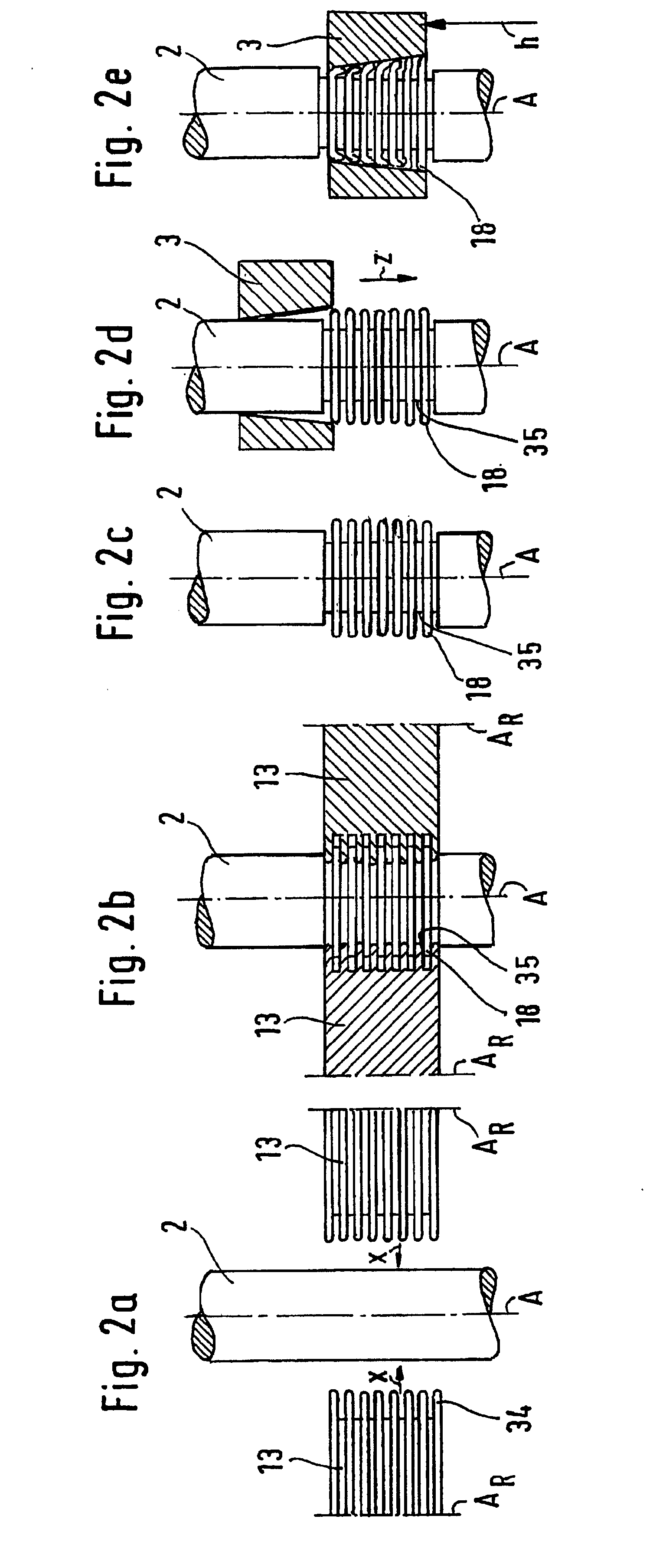
[0055] The figures show exemplary embodiments with the features of the invention in a schematic representation; they do not present any exact size relationships (or dimensional details) and merely serve to illustrate the basic principle.
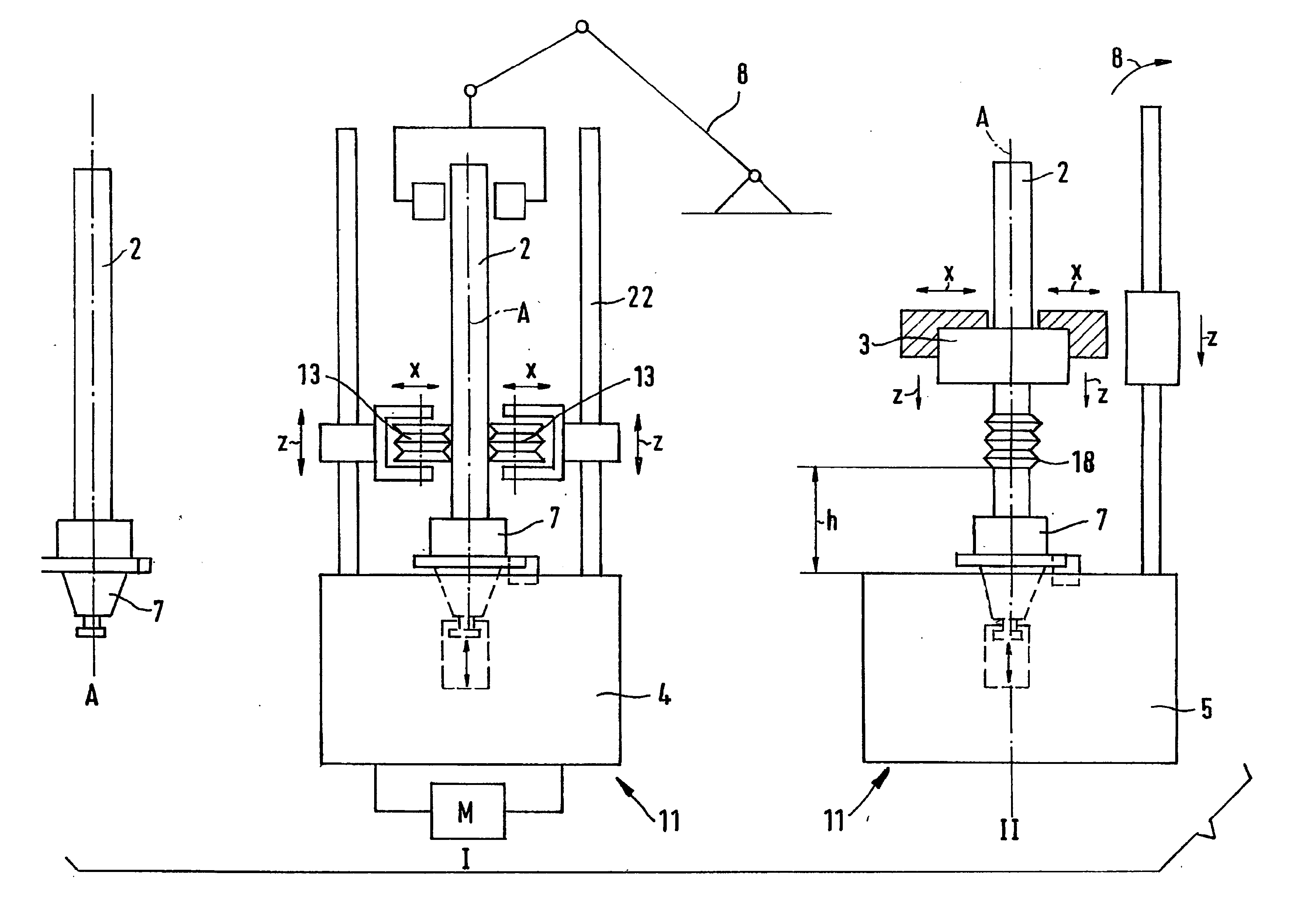
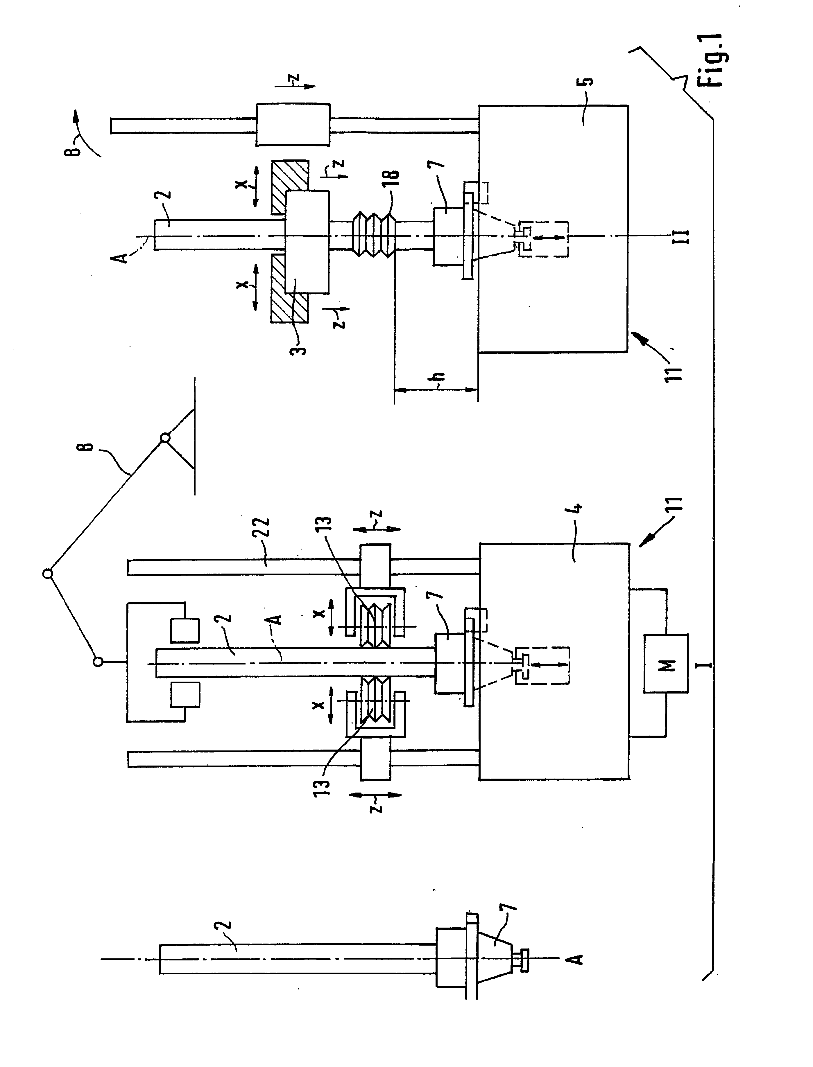
[0056] As shown in FIG. 1, a machining line for producing a camshaft 1 comprising a shaft 2 and a number of cams 3 pressed thereon substantially comprises two machining stations 11. The shaft 2 with a positioning element 7 affixed thereon is transported by means of a manipulating device 8 to the first machining station 11, a knurling station 4. The shaft 2 is fixedly clamped in the knurling station by means of the positioning element 7 and is fixed there so that it can rotate about an axis A. A motor M, preferably a controlled electric motor, ensures that the shaft 2 rotates. The knurling station 4 comprises rollers 13 which can be displaced in the x-direction and in the z-direction. During the rolling process the shaft 2 and the positioning element...
PUM
| Property | Measurement | Unit |
|---|---|---|
| Area | aaaaa | aaaaa |
| Height | aaaaa | aaaaa |
| Circumference | aaaaa | aaaaa |
Abstract
Description
Claims
Application Information
 - R&D
- Intellectual Property
- Life Sciences
- Materials
- Tech Scout
- Unparalleled Data Quality
- Higher Quality Content
- 60% Fewer Hallucinations
Browse by: Latest US Patents, China's latest patents, Technical Efficacy Thesaurus, Application Domain, Technology Topic, Popular Technical Reports.
© 2025 PatSnap. All rights reserved.Legal|Privacy policy|Modern Slavery Act Transparency Statement|Sitemap|About US| Contact US: help@patsnap.com


