
Work roll scraper for roller levelers

a scraper and roller technology, applied in the field of roller levelers, can solve the problems of uneven surface, noise, scraping edges, etc., and achieve the effect of convenient installation

Inactive Publication Date: 2007-08-09
BUTECH BLISS
View PDF22 Cites 13 Cited by
  • Summary
  • Abstract
  • Description
  • Claims
  • Application Information

AI Technical Summary

Benefits of technology

[0013]More particularly, the present invention relates to a scraper which is used to continuously clean work rolls of a roller leveler. The scrapers are constructed in a manner that allows them to nestle between adjacent work rolls. A key element of the design is the inherent spring centering of the scrapers. In this manner, the scrapers become self-supporting between the rolls, and the centering force overcomes forces that attempt to dislodge the scraper. These forces could occur as a result of a particle stuck to the roll surface. When the particle encounters the scraping blade and until the scraper “plucks” or scrapes it off, the particle causes the scraper to move up or down relative to the work roll surface. When the particle is gone, the re-centering nature of the scraper restores the scraper to its natural position.
[0029]Still yet another object of the invention is to provide a way of continuously cleaning the surface of the work rolls to inhibit the buildup of scale or “dirt”. The present invention overcomes the productivity shortcoming by providing a continuous cleaning technique while the leveler is processing strip. In other words, there is no lost production time required during the cleaning of the rolls. Continuous cleaning also has the advantage of keeping the roll surfaces clean regardless of the length of coil run and regardless of the rate of “dirt” generation.

Problems solved by technology

Continuous cleaning of the roll surfaces results in very smooth, dry, relatively high friction roll surfaces.
This higher friction causes the scraping edges to drag on the roll surface which in turn excites the scraper at its natural frequency, which translates into noise.

Method used


Image

  • Work roll scraper for roller levelers
  • Work roll scraper for roller levelers
  • Work roll scraper for roller levelers

Examples


Embodiment Construction

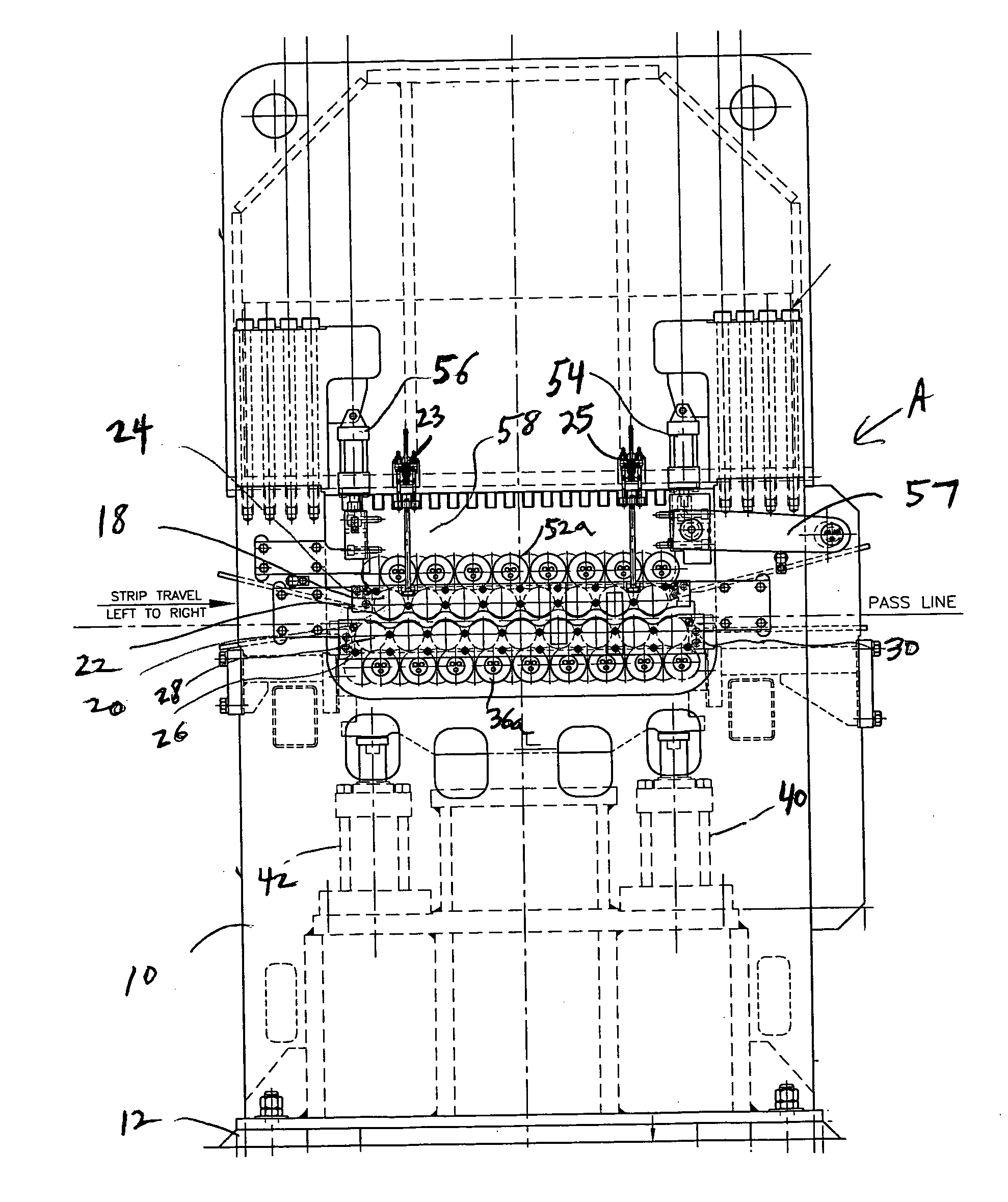
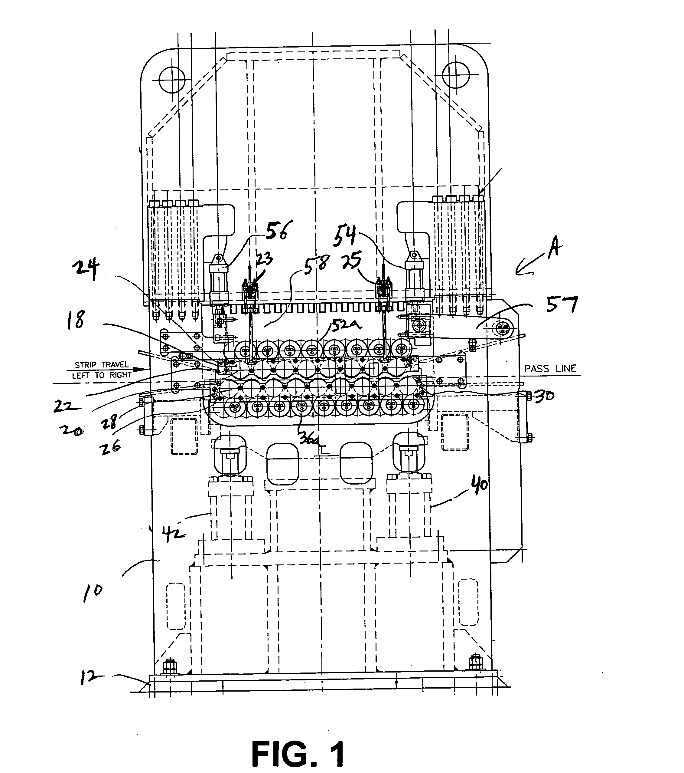
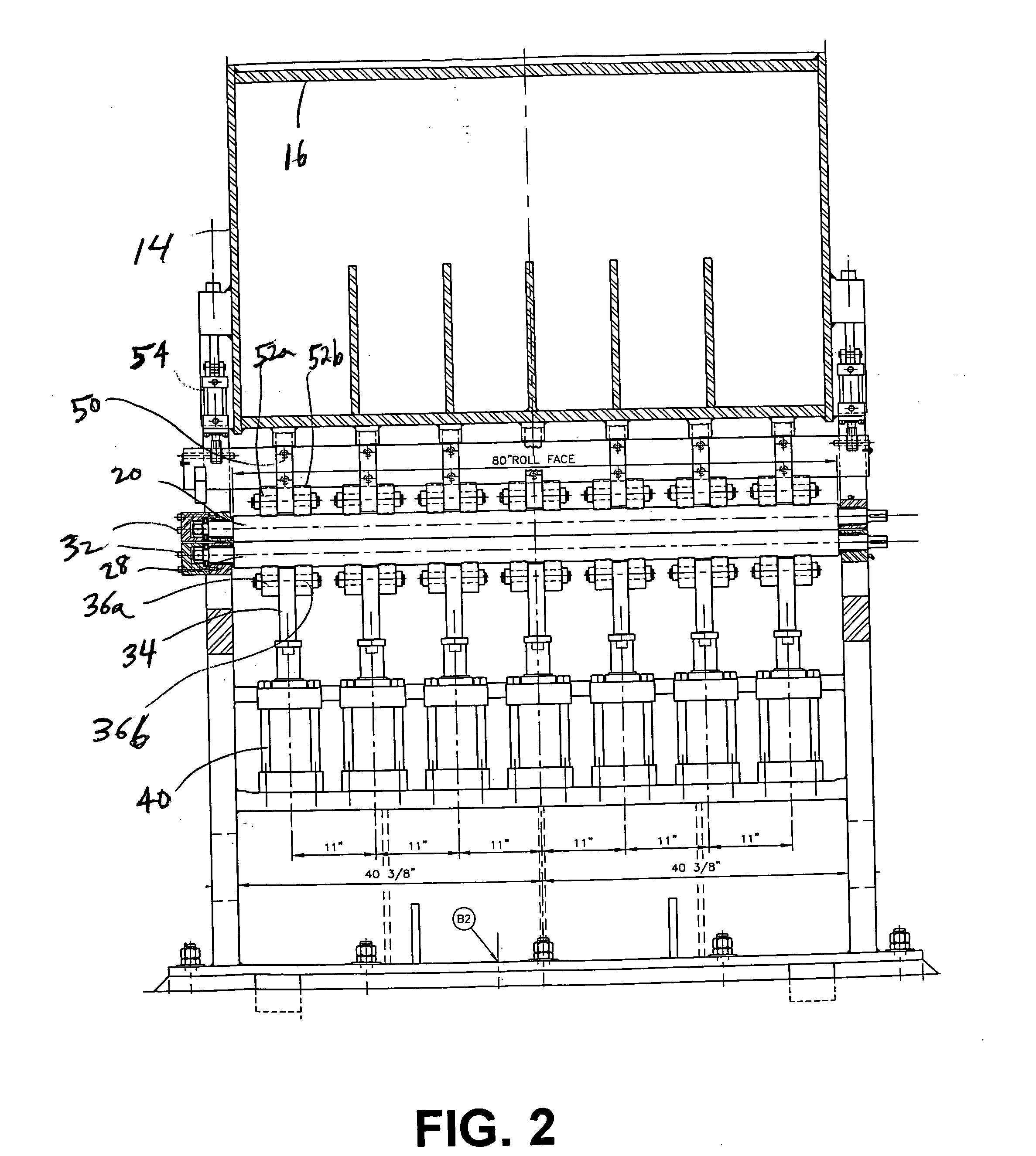
[0047]Referring now to the Figures in greater detail, and in particular to FIGS. 1 and 2, therein is shown a roller leveler A comprising a weldment frame having steel side slabs 10, welded to base slab 12 to form the lower half of the frame. As best shown in FIG. 2, the upper half of frame 10 comprises slabs 14 welded to slabs 16.

[0048]Referring specifically to FIG. 1, an upper bank 18 of a plurality of separately driven work rollers 20 is supported at opposite ends of the rollers by journal beams 22. In one embodiment of the invention, the upper work roll journals are retained vertically by clamps 23, 25 as shown in FIG. 1. In the across machine direction, the upper work roll journals are constrained by gibs to prevent side shifting of the work rolls in the across machine direction. In other embodiments, the upperwork roll journal beams use cylinders for the vertical clamp. Gibs, however, are still used for the across machine retention. The upper work rolls do not shift vertically ...


PUM

PropertyMeasurementUnit
Thicknessaaaaaaaaaa
Thicknessaaaaaaaaaa
Angleaaaaaaaaaa

Abstract

A self-retaining scraping device for continuously cleaning work rolls of a roller leveler assembly has a first wall having two angled or curved portions and a straight portion extending between the angled portions; and a second wall having two angled or curved portions and a straight portion extending between the angled portions.The first wall and second wall are connected to each other via the straight portions. The angled or curved portions of the first wall extend in an opposite direction from the angled or curved portions of the second wall. The scraping device is inserted between adjacent work rolls and has multiple scraping edges contacting outer surfaces of the work rolls to continuously clean the work rolls. The scraping device is supported by the work rolls.

Description

CLAIM OF PRIORITY[0001]This application claims priority from Provisional Application Ser. No. 60 / 766,691, filed on Feb. 6, 2006, which is incorporated by reference herein.BACKGROUND OF THE INVENTION[0002]The present invention relates to roller levelers. More particularly, it relates to self-retaining scrapers for continuously cleaning work rolls for roller levelers. Roller levelers are used to flatten metal strip, typically coming from a coil. The strip is unwound and subsequently passed through the roller leveler.[0003]A roller leveler includes multiple pairs of offset work rollers or rolls. Different size levelers can have different quantities of work rolls and back-up rolls. The upper rolls are typically offset one-half the distance between a pair of adjacent lower rolls. The metal strip passes between the upper and lower rolls. The number and spacing of the rolls depend on the thickness and strength of the metal strip. Typically, as the strip thickness decreases, the spacing of ...

Claims


Application Information

Patent Timeline
IPC IPC(8): B21D1/02
CPCB21D1/02
Inventor VASTA, SALVATORE JAMESNACKINO, ANTHONY JOSEPH
Owner BUTECH BLISS
Learn More