
Device for varing capacitance

a capacitance and device technology, applied in the direction of variable capacitors, instruments, force measurement, etc., can solve the problems of inconvenient sensing and controlling operation, reduced product reliability, etc., and achieve the effect of wide sensing range, simple structure and high sensitivity

Active Publication Date: 2007-08-09
BEIJING HANWANG PENGTAI TECH CO LTD
View PDF3 Cites 31 Cited by
  • Summary
  • Abstract
  • Description
  • Claims
  • Application Information

AI Technical Summary

Benefits of technology

[0025] The advantageous technical effect of the present invention lies in that: the device of the present invention has a simple structure, a definite zero initial value, a high sensitivity with wide sensing range. Also, the device of the present invention is capable of sensing minor variation and easy for sensing and measurement and agile in controlling.

Problems solved by technology

In fact, the capacitance value when the flexible electrode just contacts the dielectric is identical to the initial capacitance value, and it is difficult to distinguish between variation value and the initial value, which causes inconvenience in the sensing and controlling operation.
Although there is a zero initial value, the structure of the latter Japanese patent is complicated and troublesome for manufacturing and production, and the reliability of the product is reduced.

Method used


Image

  • Device for varing capacitance
  • Device for varing capacitance
  • Device for varing capacitance

Examples


Embodiment Construction

[0036] Reference will now be made in detail to the preferred embodiments of the present application. It can be appreciated that various modification in many different ways can be made to the following illustrative embodiments of the present invention without departing the principle of the present invention disclosed herein. Therefore, the scope of the present invention will in no way be limited to the special embodiments in the following.

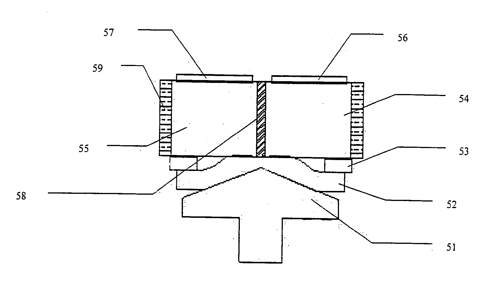
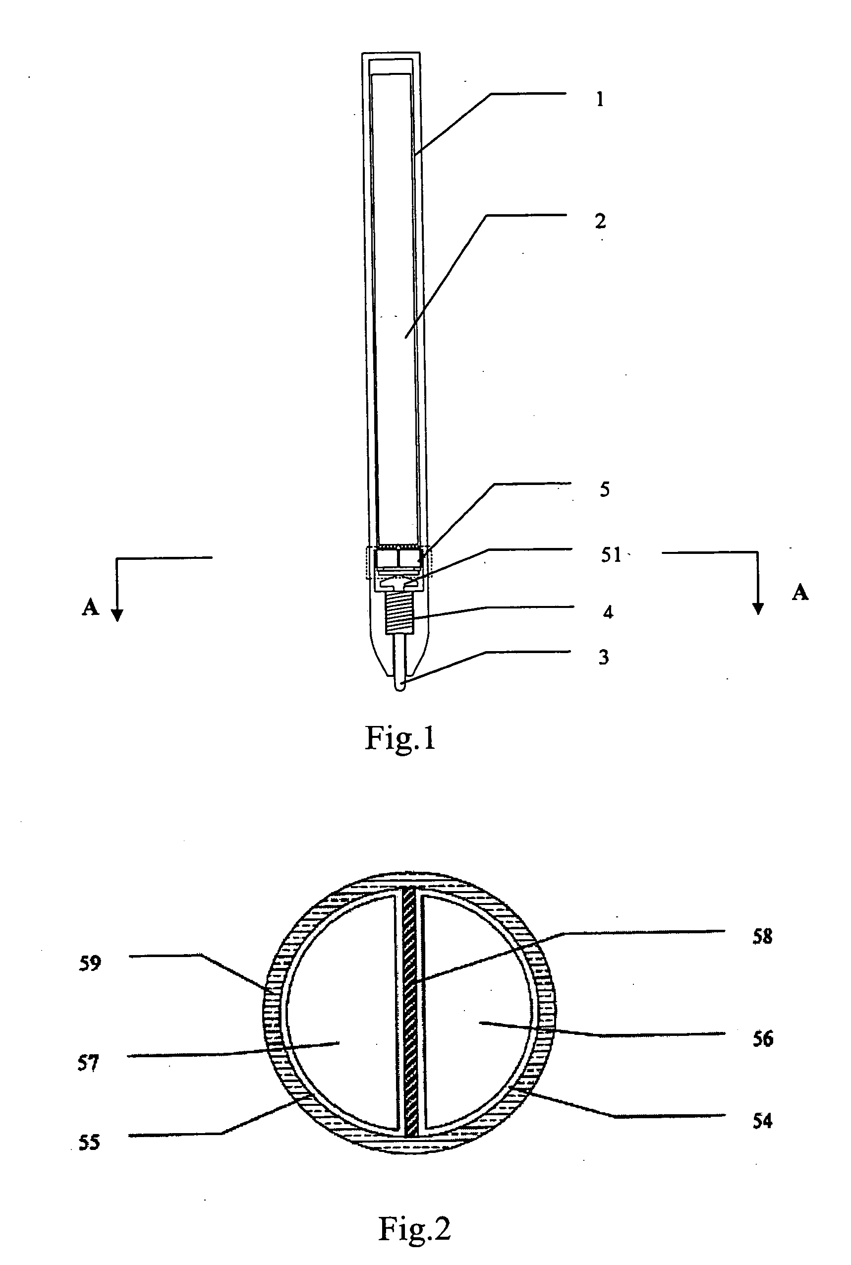
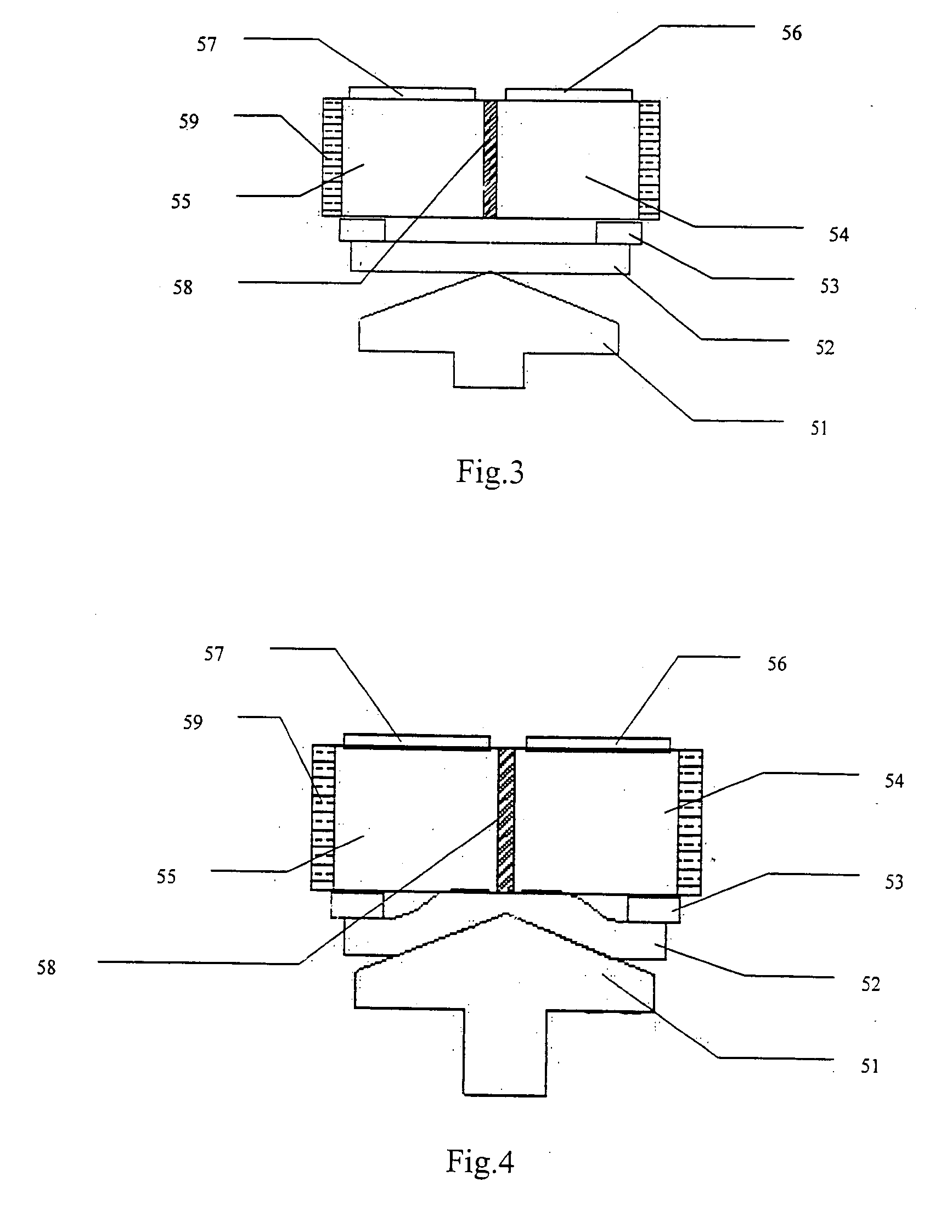
[0037] The device of the present invention is adapted to be used in the handwriting pen apparatus for inputting data to a computer. The present embodiment employs an device as shown in FIG. 1, which comprises a pen body 1, a circuit board 2 in the pen body 1, a pen tip 3 in the front end of the pen body, an inductive coil 4 and a dielectric structure 5. A contact probe 51 is integrated with the pen tip 3 as a whole. The inductive coil 4 is disposed between the contact probe 51 and the pen tip 3.

[0038]FIG. 2 is a sectional view along the line A-A o...


PUM


Abstract

Disclosed is a device for varying capacitance which pertains to the field of application of electronic devices and components. The technical essentials of the present invention lie in that: two dielectrics are disposed in parallel with an isolation layer interposed therebetween; the two dielectrics each are connected to an electrode at the same one end face thereof; the other end face of each of the two dielectrics is provided with an elastic conductive pad; a gasket is provided between the two dielectrics and the elastic conductive pads. The relative position and compressed area between the elastic conductive pads and the dielectrics vary according to the magnitude of the external force so that the capacitance between the electrodes of the dielectrics is varied accordingly within a certain range. Therefore, once the value and the variation of the capacitance between the electrodes are measured, the magnitude and the status of the external force which brings about the variation of the capacitance can be obtained. The device of the present invention has a simple structure and high sensitivity. Also, it has a definite zero initial value and a maximum value of the capacitance, and therefore is easy for handing and measurement.

Description

BACKGROUND OF THE INVENTION [0001] 1. Field of the Invention [0002] The present invention relates to a device for varying capacitance, and reflecting pressure-variation on it by means of the variation of the capacitance, which pertains to the field of the application of electronic devices and components. [0003] 2. Description of the Related Art [0004] With the increasing improvement in the design of the consumptive electronic products as well as the increment of the demand of the user, there are more and more occasions in which a varying external physical quantity needs to be measured, controlled and responded. Pressure sensing techniques are examples adopted in such occasions, which are widely used in many technical fields, such as a handwriting pen in the input apparatus of a computer. When the writer uses the handwriting pen, a real time feedback to the pressure is required. That is, the variation of the magnitude of the acting force upon writing should be quickly and timely refl...

Claims


Application Information

Patent Timeline
IPC IPC(8): G01B7/16
CPCG06F3/03545H01G5/014H01G5/0136H01G5/011H03G5/16G06F3/0354
Inventor LIU, YINGJIANWANG, HONGGANGSONG, BOJUNZHAO, LIANG
Owner BEIJING HANWANG PENGTAI TECH CO LTD
Learn More