Automotive air conditioning system

a technology for air conditioning systems and automobiles, which is applied in vehicle maintenance, vehicle cleaning, transportation and packaging, etc., can solve the problems of inconvenient deterioration of the comfort of the occupants, difficulty in maintaining an appropriate preset proportion,

Inactive Publication Date: 2007-08-09
DENSO CORP
View PDF2 Cites 28 Cited by
  • Summary
  • Abstract
  • Description
  • Claims
  • Application Information

AI Technical Summary

Benefits of technology

[0022] In the process, the gap (T) is formed along the door diameter between a circumferential end portion of the door surface (25c) and the seal rib (28), and therefore the size of the gap (T) is basically not affected by the rotational position of the rotary door (25). Even in the case where the rotary door (25) is rotated slightly under air pressure in foot mode, therefore, the gap (T) remains substantially the same size. As a result, the defroster blowout air amount and the foot blowout air amount in foot mode can be maintained in a preset proper proportion.
[0023] Also, the warm air flowing into the...

Problems solved by technology

As a result, it becomes difficult to maintain an appropriate preset proportion between the defroster blowout air amount and the foot blowout air amount...

Method used


Image

  • Automotive air conditioning system
  • Automotive air conditioning system
  • Automotive air conditioning system

Examples


first embodiment

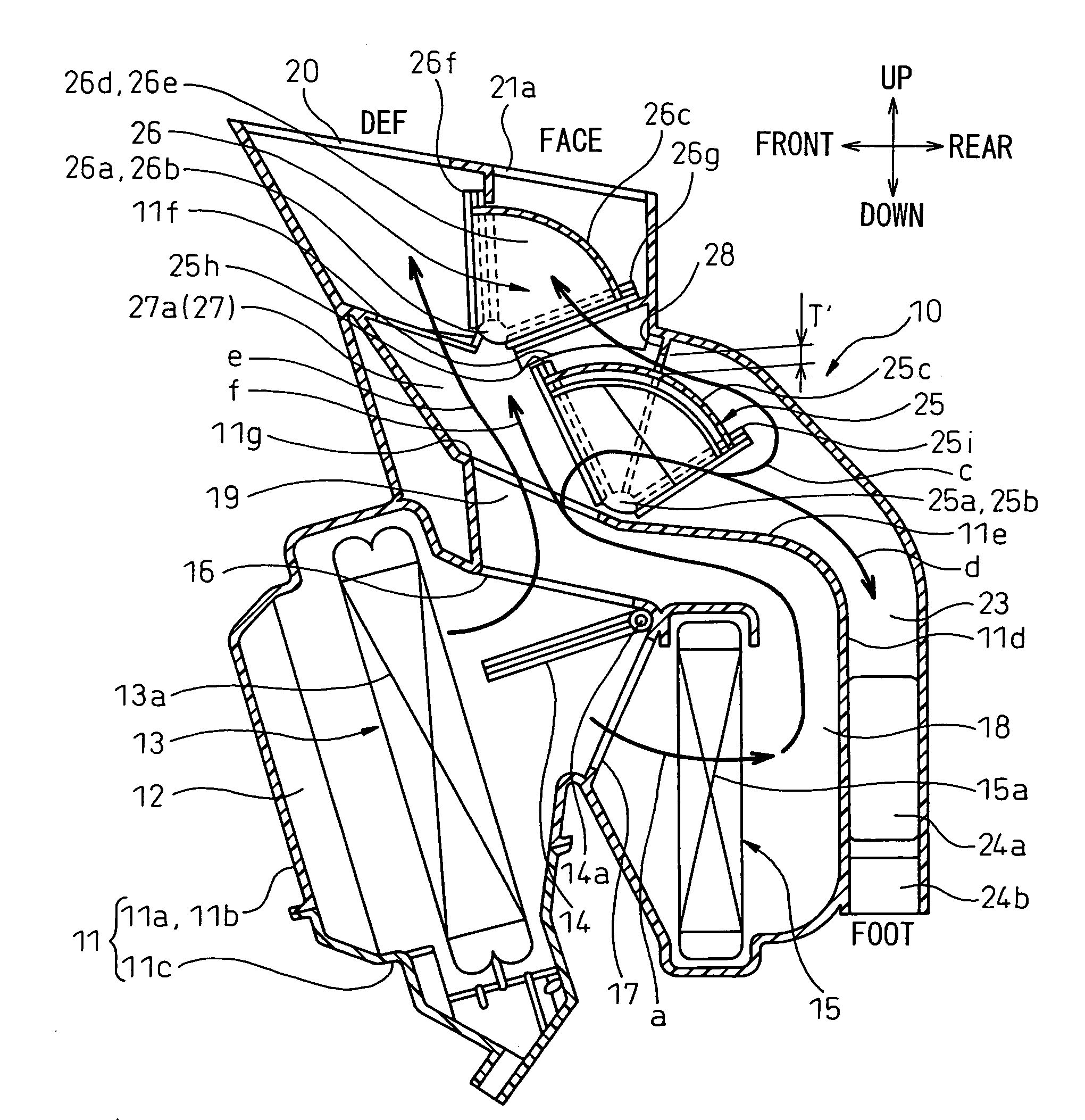
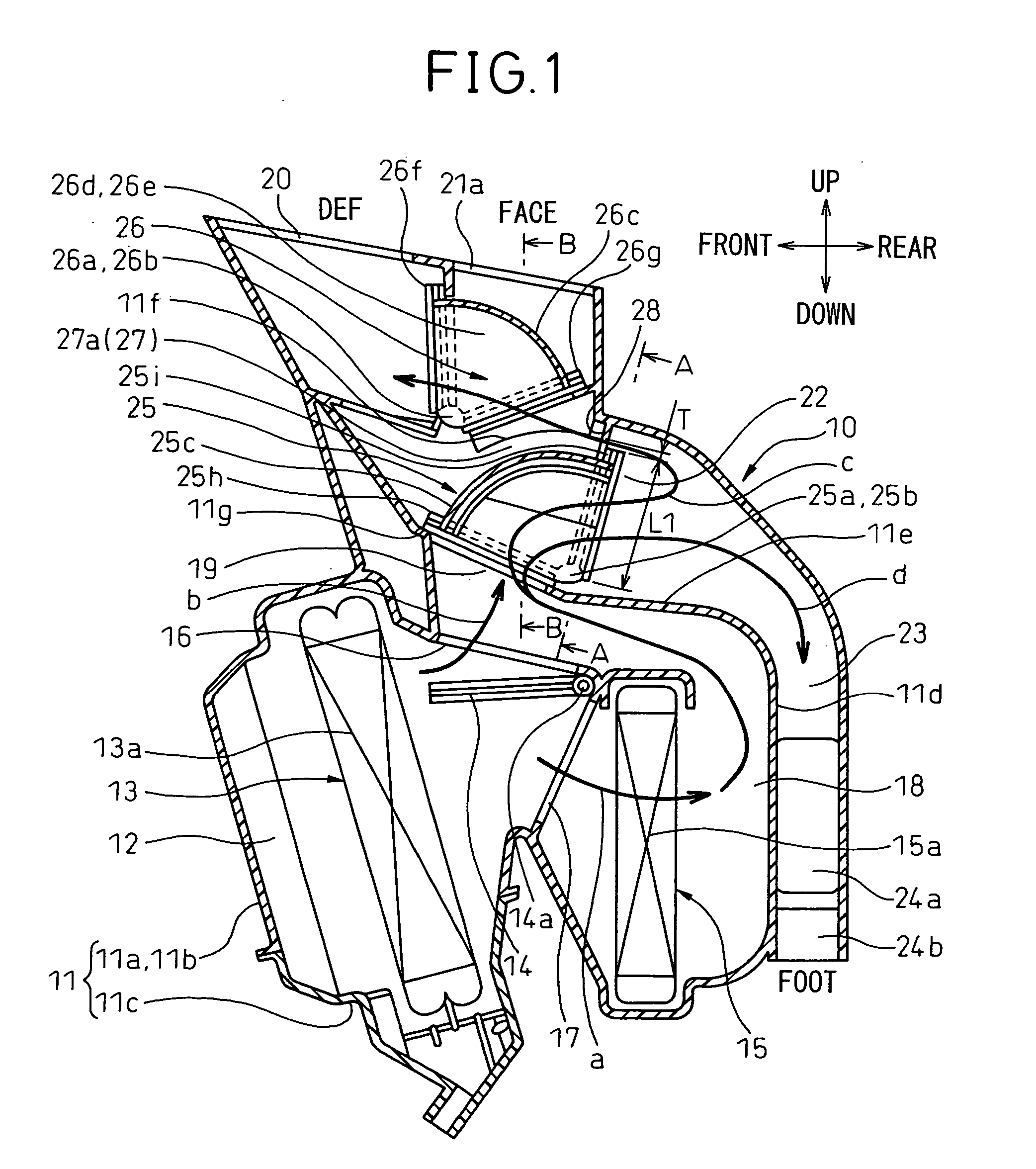
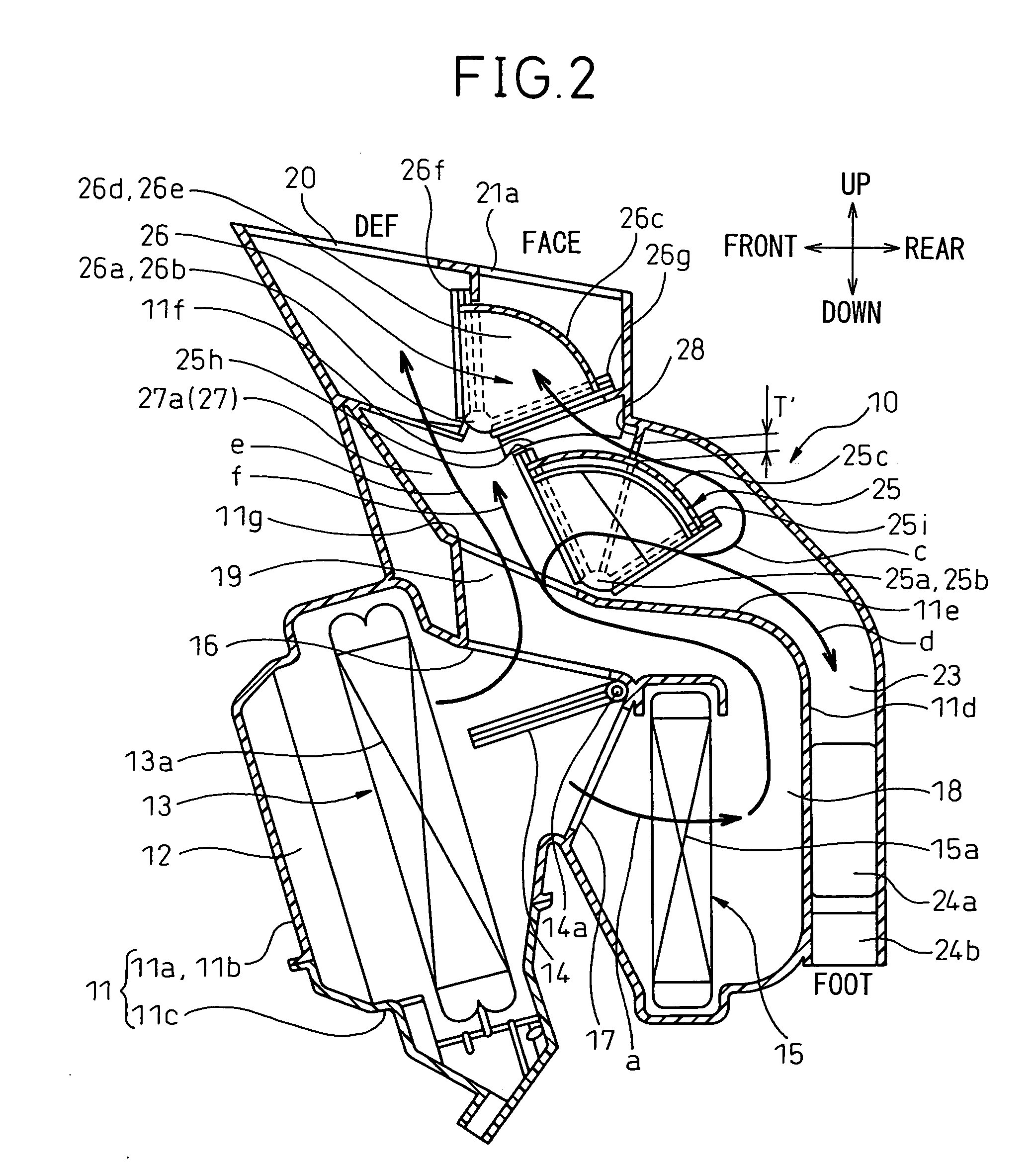
[0065] FIGS. 1 to 8 show a first embodiment of the invention. FIGS. 1 to 3 are longitudinal sectional views of an air-conditioning unit 10 accommodating a heat exchanger unit and constituting an inside unit of a air conditioning system for an automotive vehicle. FIG. 1 shows the operation in foot mode and FIG. 2 the operation in foot / defroster mode. FIG. 3 shows the operation in defroster mode constituting a blowout mode for closing up the foot opening.

[0066] The air-conditioning unit 10 is arranged inside the instrument panel (not shown) in the front compartment and substantially in the transversely (laterally) central portion of the vehicle. In FIGS. 1 to 3, the arrows indicating “up”, “down”, “front” and “rear” represent the directions as viewed from the air conditioning system mounted on the vehicle. The inside unit of the automotive air conditioning system roughly includes an air-conditioning unit 10 located substantially at the central portion and a blower unit, not shown, ar...

second embodiment

[0158]FIG. 9 shows the first rotary door 25 for the foot application according to a second embodiment. According to the second embodiment, the radius R of the central door surface 25c of the first rotary door 25 is kept constant over the whole circumferential area. Of the two seal units 25h, 25i of the first rotary door 25, therefore, the projection height D′ of the seal unit 25h of the end near to the defroster opening 20 is set larger than the projection height D of the seal unit 25i of the end near to the foot opening 22 (D′>D).

[0159] As a result, the maximum size L1, along the door diameter, of the end portion (end portion near to the vehicle rear end) near to the foot opening 22 is smaller than the maximum size L2, along the door diameter, of the end portion (end portion near to the vehicle front) of the defroster opening 20 (L12), where L1=R+D, L2=R+D′.

[0160] Also in the second embodiment, the gap T shown in FIGS. 1, 6 can be formed and can be closed in defroster mode, by se...


PUM


Abstract

An automotive air conditioning system is disclosed. At the foot mode position of a rotary door 25, a gap T is formed along the door diameter between a circumferential end of a door surface 25c of the rotary door 25 and a seal rib 28 of a case 11. The flow path of a foot opening 22 communicates with a defroster opening 20 through the gap T. At the defroster mode position of the rotary door 25, on the other hand, the other circumferential end of the door surface 25c comes into contact with the seal rib 28 and closes the gap T, and the door surface 25c closes up the foot opening 22. Even upon slight rotation of the foot rotary door under the air pressure of the foot mode, therefore, the defroster blowout air amount and the foot blowout air amount are kept in a predetermined proportion.

Description

BACKGROUND OF THE INVENTION [0001] 1. Field of the Invention [0002] This invention relates to a blowout mode switching mechanism for an automotive air conditioning system. [0003] 2. Description of the Related Art [0004] Japanese Unexamined Patent Publication No. 2004-155263 proposes a conventional automotive air conditioning system in which a defroster opening 20, a center face opening 21a and a foot opening 22 are opened / closed by two rotary doors 25, 26 as shown in FIGS. 10 to 12. [0005] Specifically, the foot opening 22 and a defroster / face communication path 27a are opened / closed by the first rotary door 25, and the defroster opening 20 and the center face opening 21a are arranged downstream of the communication path 27a and are opened / closed by the second rotary door 26. [0006] The rotary doors 25, 26 have door surfaces 25c, 26c rotatable integrally with each of the rotary shafts 25a, 25b, 26a, 26b. The door surfaces 25c, 26c are positioned a predetermined distance radially awa...

Claims


Application Information

Patent Timeline
IPC IPC(8): B60H3/00B60H1/00
CPCB60H1/00842B60H1/00678
Inventor MASATSUGU, AKIRA
Owner DENSO CORP
Why Eureka
Try Eureka