
Beverage Container Vent Mechanism Including Perforated Elastic Membrane And Support Plate

a technology of elastic membrane and support plate, which is applied in the direction of feeding bottles, teasers, etc., can solve the problems of undesirable leakage, requiring relatively complicated and expensive manufacturing equipment, and generating bubbles that may be subsequently consumed by babies

Inactive Publication Date: 2007-08-09
MEDELA HLDG AG +1
View PDF25 Cites 19 Cited by
  • Summary
  • Abstract
  • Description
  • Claims
  • Application Information

AI Technical Summary

Benefits of technology

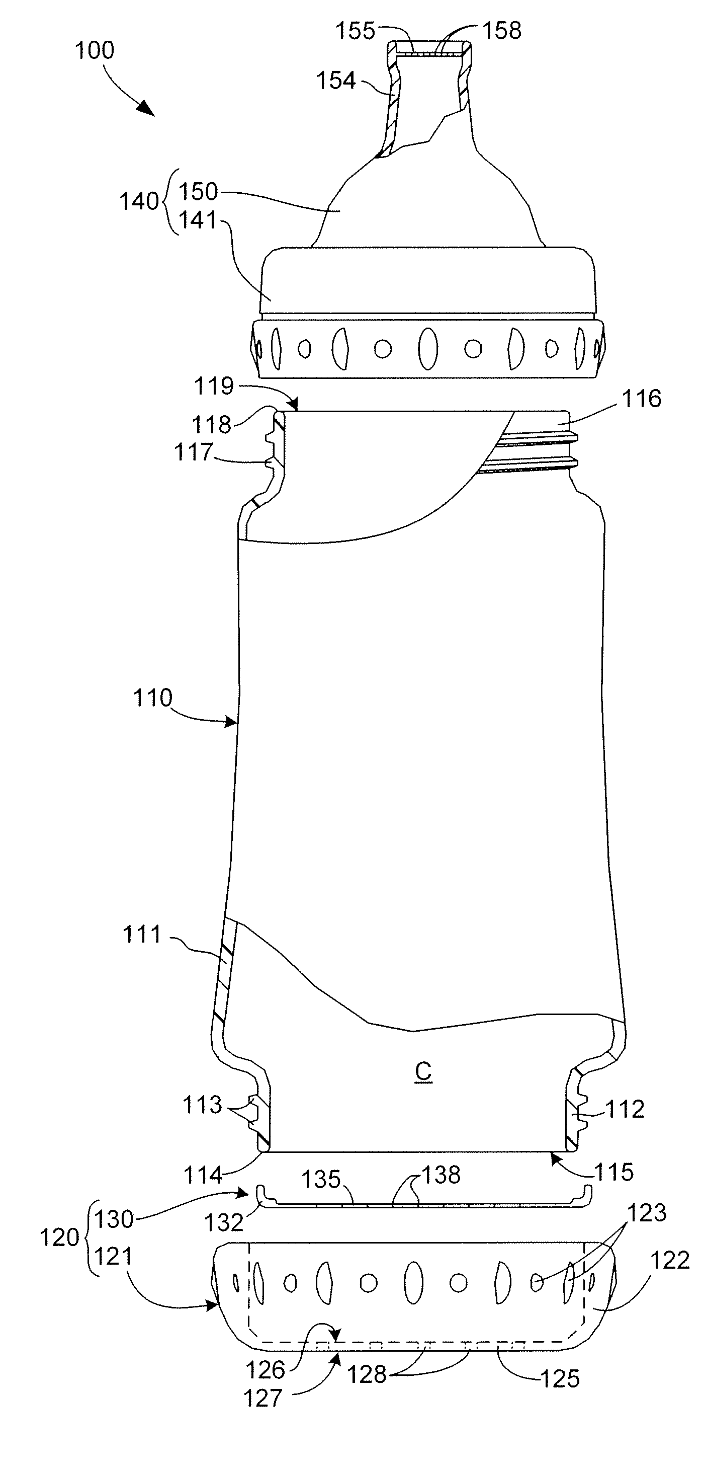
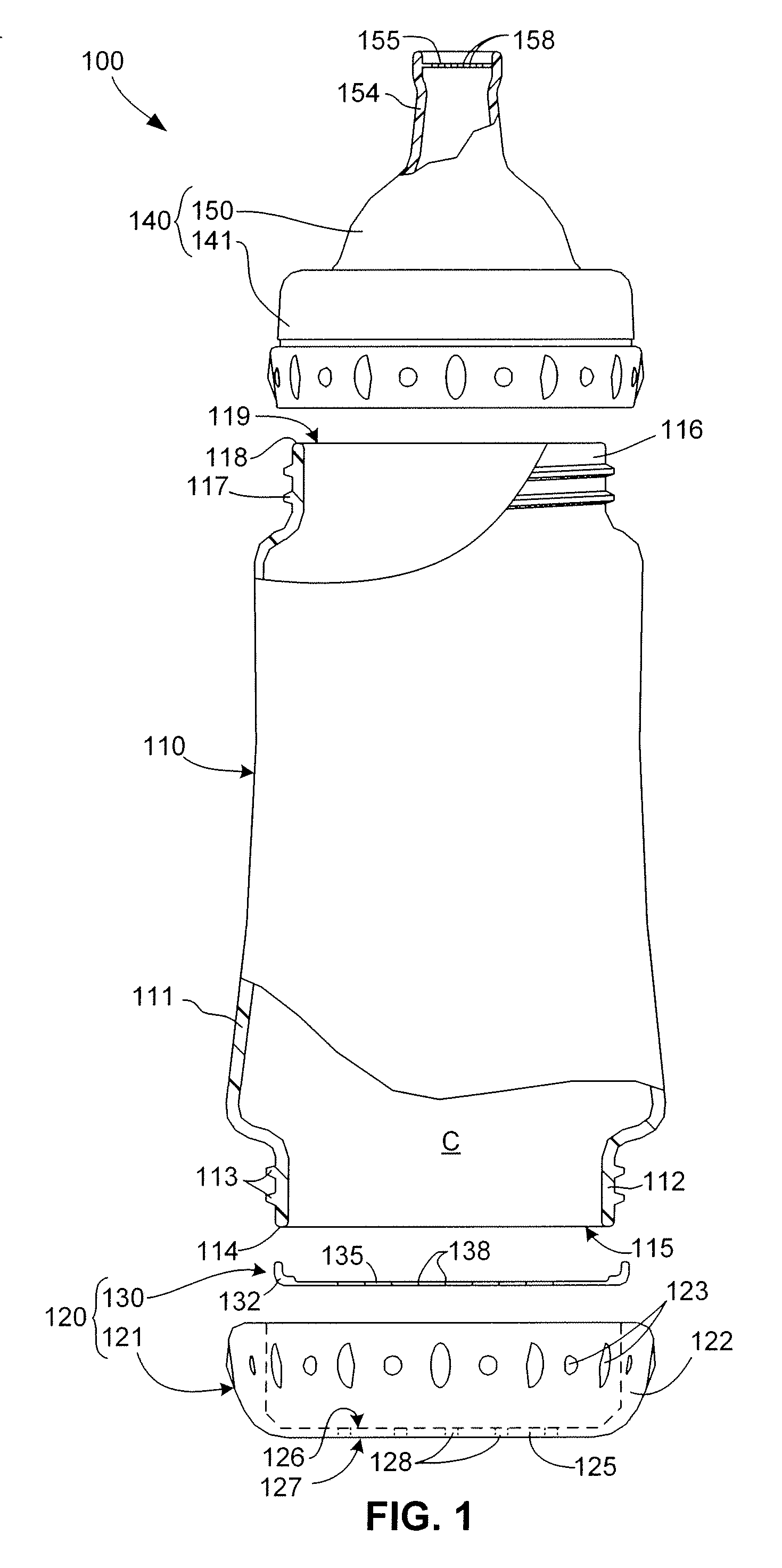
[0007] The present invention is directed to beverage containers that utilize vent mechanisms to allow air into a central chamber as a beverage contained therein is drawn out, thereby equalizing the internal pressure in the beverage container.
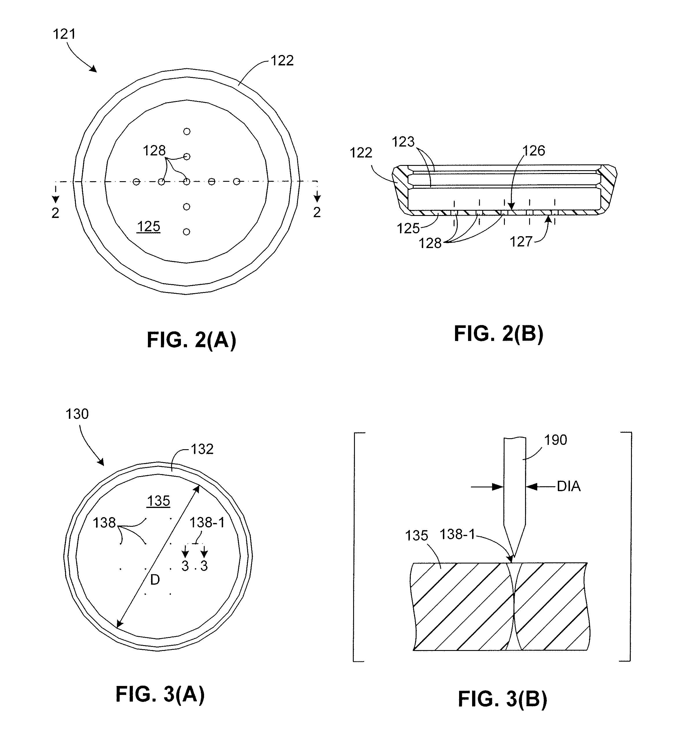
[0008] In accordance with an embodiment of the present invention, a vent mechanism includes a rigid support plate having one or more open vent holes (openings), and a flow control member including a membrane that is supported between the support plate and a storage chamber of the beverage container. The membrane is a thin, flat elastic sheet that is perforated to include one or more normally-closed pinholes. Because the pinholes are formed on a flat surface, manufacturing of beverage containers in accordance with the present invention is greatly simplified over conventional venting mechanisms that utilize domed diaphragms. In addition, because the pinholes are formed using pins that do not produce slits in the membrane material that can become weakened and / or trap deposits that can prevent slit flap closure, the vent mechanism of the present invention facilitates leak-free operation that is substantially more reliable than that of slit-based conventional venting mechanisms.
[0010] In accordance with an alternative specific embodiment of the present invention, a beverage container assembly includes a container body and an elongated, silicone fluid containment member that is inserted inside the container body. The container body has an upper cylindrical neck portion and a lower rigid support plate defining vent holes, where the lower support plate is connected to the neck portion by elongated ribs or a continuous side wall. The silicone fluid containment member includes relatively thick, substantially cylindrical side walls defining an upper opening at its upper end and having a relatively thin (in relation to the side walls) pinhole membrane integrally formed at its opposing lower end. The silicone fluid containment member is inserted into the shell-like body such that the pinhole membrane abuts the rigid support plate and the upper opening is disposed in the neck portion. A beverage is then inserted into the silicone fluid containment member. A cap including a flow control member is then mounted (e.g., screwed) onto the neck to seal the beverage, and to press the silicone fluid containment member into the shell-like body such that the pinhole membrane is pressed against the rigid support wall. The pinhole membrane functions as described above to vent air into the silicone fluid containment member as beverage is drawn out through the flow control member (i.e., nipple or nozzle). An advantage of this embodiment is that the beverage is entirely contained in silicone, which is believed to provide certain health benefits over some commonly used plastics.
[0011] In accordance with another alternative embodiment of the invention, a beverage container assembly includes a resilient container body, a one-way vent valve for allowing air inside the container body, a flexible bladder (fluid reservoir) that is mounted inside the container body for holding a beverage, and a flow control (e.g., nozzle) assembly mounted over an open end of the bladder and secured to the container body. In one specific embodiment the container body includes a rigid support plate integrally formed at its lower end, and the one-way vent valve includes an elastomeric membrane with pinholes formed as described above mounted on an inside surface of the container body over the rigid support plate. During use, manually squeezing the container body causes its internal pressure to increase (i.e., because the one-way vent valve prevents air from escaping the container body), thereby forcing the liquid out of the bladder through the flow control member disposed over the upper end of the bladder. When the manually applied pressure is released, the container body resiliently returns to its original shape, drawing air into the container body through the one-way vent valve. In effect, the one-way vent valve cooperates with the container body to provide a pump for forcing liquid from the bladder through the flow control element, thereby facilitating beverage consumption with the beverage container in any orientation (e.g., upright, horizontal, or upside-down). In another specific embodiment, the flow control assembly includes a one-way valve that allows beverage to exit the bladder, but prevents air flow into the bladder when the manually applied pressure is released. An advantage of this embodiment is that the beverage is entirely contained in the bladder, thereby providing health benefits similar to those discussed above. In addition, because the bladder collapses toward the nozzle, the present embodiment facilitates beverage consumption with the container in an upright position.

Problems solved by technology

A problem with this type of conventional venting mechanism is that the air entering the baby bottle passes through the remaining milk or formula, causing the generation of bubbles that may be subsequently consumed by the baby.
A problem with such domed diaphragms is that they typically require relatively complicated and expensive manufacturing equipment.
In addition, the slit-like vent openings are known to weaken with repeated use and / or to trap solid material that eventually produces tearing along the edges of the slits, which can ultimately cause undesirable leakage.

Method used


Image

  • Beverage Container Vent Mechanism Including Perforated Elastic Membrane And Support Plate
  • Beverage Container Vent Mechanism Including Perforated Elastic Membrane And Support Plate
  • Beverage Container Vent Mechanism Including Perforated Elastic Membrane And Support Plate

Examples


Embodiment Construction

[0025] The present invention is described below with specific reference to a baby bottle assembly, which represents one type of beverage container that benefits from the present invention. As used herein, directional terms such as “upper”, “upwards”, “lower”, “downward”, “front”, “rear”, are intended to provide relative positions for purposes of description, and are not intended to designate an absolute frame of reference. In addition, the phrases “integrally connected” and “integrally molded” is used herein to describe the connective relationship between two portions of a single molded or machined structure, and are distinguished from the terms “connected” or “coupled” (without the modifier “integrally”), which indicates two separate structures that are joined by way of, for example, adhesive, fastener, clip, or movable joint. Various modifications to the preferred embodiment will be apparent to those with skill in the art, and the general principles defined herein may be applied t...


PUM


Abstract

A beverage container assembly includes a thin, silicone membrane that is perforated with multiple pinholes and is mounted on a rigid support plate defining multiple vent holes. The silicone membrane rests against an inside surface of the support plate when the pressure inside the container is equal to or greater than the surrounding environment, and the pinholes remain closed to prevent beverage leakage. When beverage is drawn from the container, the resulting pressure differential causes the membrane to bend inward, which opens the pinholes to allow venting of air into the container. The membrane is formed at the end of an elongated silicone fluid containment member that forms a liner inside a container body.

Description

RELATED APPLICATION [0001] The present application is a continuation-in-part of U.S. patent application Ser. No. 11 / 212,154 filed by James W. Holley, Jr. and Patrick T. Bever on Aug. 26, 2005.FIELD OF THE INVENTION [0002] The present invention relates to beverage containers, and more specifically it relates to vent mechanisms for regulating internal pressure of bottle-type beverage containers. RELATED ART [0003] Bottle-type beverage containers, such as baby bottles, utilize various conventional venting mechanisms that prevent vacuum generation by admitting air into the container to replace the volume of liquid drawn out by a feeding baby through a nipple, thereby allowing a baby to feed without stopping to allow air into the bottle through the nipple. [0004] One such conventional venting mechanisms utilized in baby bottle assemblies includes a slit-like vent hole formed in the flange surrounding a baby bottle nipple, which is secured to a threaded neck of the baby bottle by way of a...

Claims


Application Information

Patent Timeline
Patent Type & Authority Applications(United States)
IPC IPC(8): A61J11/00A61J9/04A61J9/00
CPCA61J9/04A61J11/04A61J11/009
Inventor HOLLEY, JAMES W. JR.BEVER, PATRICK T.
Owner MEDELA HLDG AG
Learn More