Vehicular Component Control Methods Based on Blind Spot Monitoring

a control method and vehicle technology, applied in the field of collision avoidance systems and methods, can solve the problems of increasing the calculation errors, reducing the sensing accuracy, and only working with the sensor to compensate for the pitch of the vehicl

Inactive Publication Date: 2007-08-09
AMERICAN VEHICULAR SCI
View PDF56 Cites 295 Cited by
  • Summary
  • Abstract
  • Description
  • Claims
  • Application Information

AI Technical Summary

Problems solved by technology

This prior art vehicle speed determination system, however, suffers from the problem that when the speed of a vehicle is sensed by the Doppler sensor mounted on the vehicle body, vehicle pitching motion, for example, changes the wave transmission angle θ decreasing the sensing accuracy.
However, such a sensor only works to compensate for vehicle pitch.
When the velocity sensor is mounted high on the vehicle, where it is protected from contamination, it will frequently receive reflections from the ground that are at a significant distance from the vehicle and can therefore be at a significantly different altitude and thus at a significantly different effective θ thus adding additional errors to the calculation.
The problem is exacerbated in the construction industry when the Doppler sensor is mounted at a level low on the vehicle such that there is a strong likelihood that mud may stick to the sensor or the sensor may get damaged by striking rocks etc.
However, if these problems are solved by mounting a Doppler radar-based velocity sensor high on the vehicle, there can be a problem where the RF radiation exceeds permitted levels or interfere with similar systems on other vehicles at the same worksite.
However, this is done to reduce system cost and it is not used to determine the distance to the reflecting surface.
No attempt is made to compensate for vehicle pitch or for changes in ground elevation.
Since this angle is a critical factor in the Doppler velocity equation, all prior art systems will suffer from this inaccuracy.
Nevertheless, the inventions herein can contribute to safe driving in these conditions, if such driving is attempted, since an indication will be obtained by the system based on the elliptical reflections from the laser diode indicating that the visibility is unacceptable.
“Out-of-position” as used for an occupant will generally mean that the occupant, either the driver or a passenger, is sufficiently close to an occupant protection apparatus (airbag) prior to deployment that he or she is likely to be more seriously injured by the deployment event itself than by the accident.
It may also mean that the occupant is not positioned appropriately in order to attain the beneficial, restraining effects of the deployment of the airbag.

Method used


Image

  • Vehicular Component Control Methods Based on Blind Spot Monitoring
  • Vehicular Component Control Methods Based on Blind Spot Monitoring
  • Vehicular Component Control Methods Based on Blind Spot Monitoring

Examples


Embodiment Construction

1. Exterior Monitoring

[0263] 1.1 General

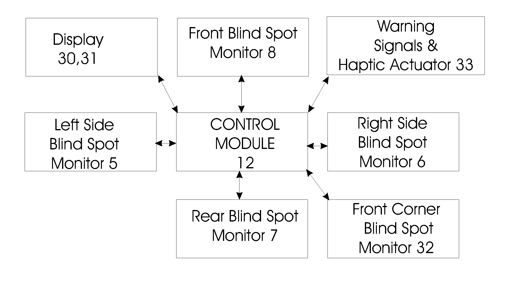
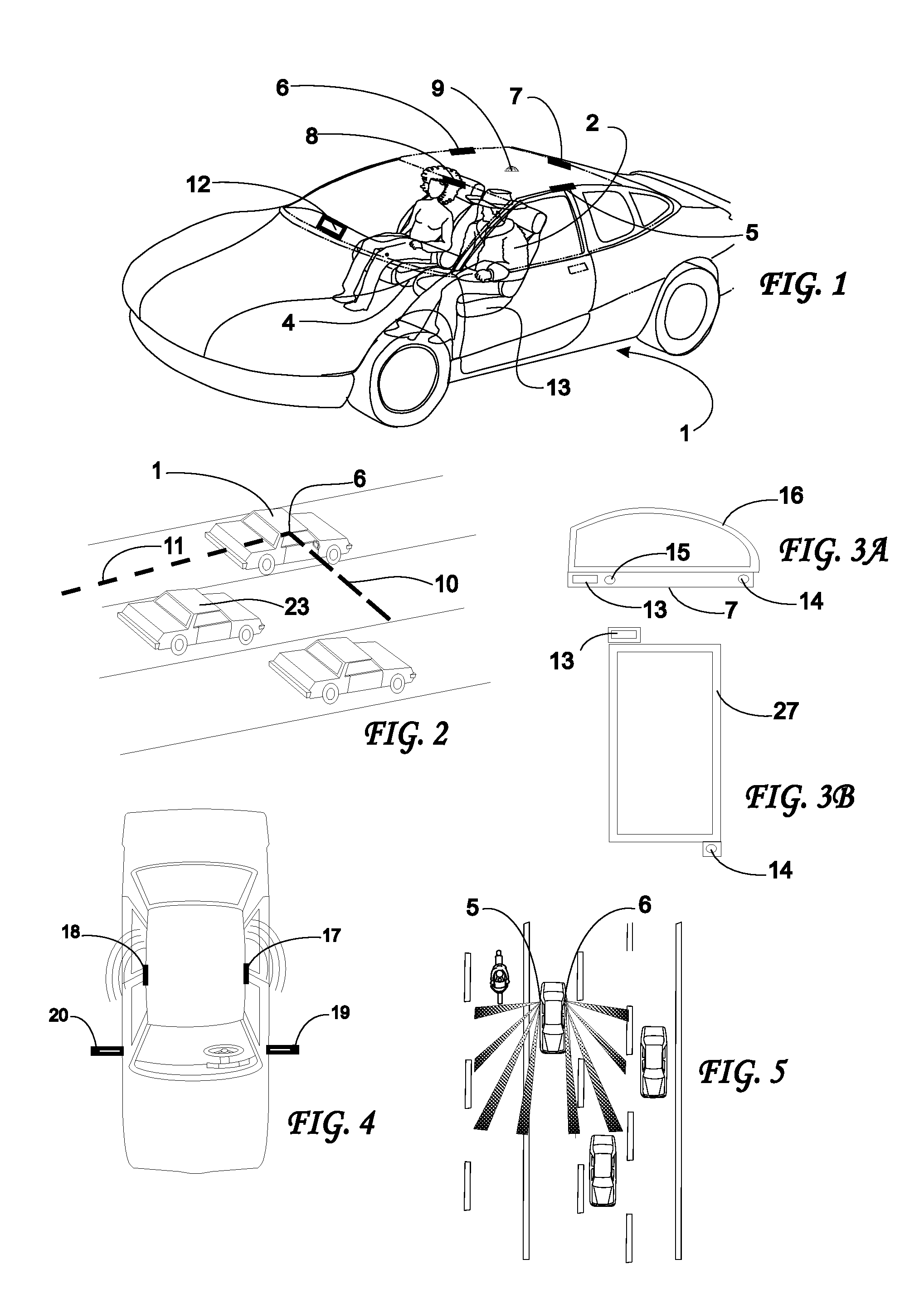
[0264] Referring now to the drawings wherein the same reference numerals refer to like elements, a perspective semi-transparent view of an automobile is shown generally as 1 in FIG. 1. A driver 2 of the automobile sits on a front seat 4. Five transmitter and / or receiver assemblies 5, 6, 7, 8 and 9 are positioned at various places with views of the environment surrounding the vehicle. A processor such as control circuitry 12 is connected to the transmitter / receiver assemblies 5-9 by appropriate wires, not shown, or wirelessly and controls the transmission of waves or energy from the transmitter portion of the assemblies 5-9 and captures the return signals received by the receiver portion of the assemblies 5-9. Control circuitry 12 usually contains one or more analog to digital converters (ADCs) or frame grabbers, a microprocessor containing sufficient memory and appropriate software including pattern recognition algorithms, and other appropr...


PUM


Abstract

Method for controlling a vehicular system based on the presence of an object in an environment around a vehicle with one goals being to prevent collisions between the vehicle and any objects. Infrared light is emitted from the vehicle into a portion of the environment around the vehicle and received by a sensor on the vehicle. Distance between the vehicle and an object from which the infrared light is reflected is determined based on the emission of the infrared light and reception of the infrared light. The presence of and an identification of the object from which light is reflected is / are determined based at least in part on the received infrared light. The vehicular system is controlled or adjusted based on the determination of the presence of an object in the environment around the vehicle and the identification of the object and the distance between the object and the vehicle.

Description

CROSS-REFERENCE TO RELATED APPLICATIONS [0001] This application is a divisional of U.S. patent application Ser. No. 11 / 111,474 filed Apr. 21, 2005, now U.S. Pat. No. 7,209,221, which is a continuation-in-part of U.S. patent application Ser. No. 10 / 754,014 filed Jan. 8, 2004, now U.S. Pat. No. 6,885,968, which claims priority under 35 U.S.C. §119(e) of U.S. provisional patent application Ser. No. 60 / 442,204 filed Jan. 24, 2003 and is a continuation-in-part of U.S. patent application Ser. No. 09 / 851,362 filed May 8, 2001, now U.S. Pat. No. 7,049,945, which claims priority under 35 U.S.C. §119(e) of U.S. provisional patent application Ser. No 60 / 202,424 filed May 8, 2000. These applications are incorporated by reference herein in their entirety.FIELD OF THE INVENTION [0002] This invention relates generally to collision avoidance systems and methods and more specifically to systems and methods for detecting and obtaining information about objects in the various blind spots that surround...

Claims


Application Information

Patent Timeline
Patent Type & Authority Applications(United States)
IPC IPC(8): B60Q1/00G01S13/00E05F15/00H04N7/18
CPCB60Q9/008B60W30/095B60W30/16G01S7/4802G01S11/12G08G1/16G01S17/48G01S17/89G01S17/936G01S2013/9332G01S17/023G01S7/417G08G1/165G08G1/166G08G1/167G01S17/86G01S17/931G01S2013/9315
Inventor BREED, DAVID S.DUVALL, WILBUR E.JOHNSON, WENDELL C.
Owner AMERICAN VEHICULAR SCI
Why Eureka
Try Eureka