Device for dynamic illumination

a dynamic illumination and device technology, applied in static indicating devices, instruments, semiconductor lamps, etc., can solve the problems of redundant light effects, radio noise and noise along the circuit, redundant light effects, etc., to increase the variety of light effects, increase attractiveness, and increase the dynamic nature of light effects

Inactive Publication Date: 2007-08-09
SINYUGIN ANDREI V +3
View PDF2 Cites 8 Cited by
  • Summary
  • Abstract
  • Description
  • Claims
  • Application Information

AI Technical Summary

Benefits of technology

[0008] Accordingly, it is an object of the present invention to provide a device for dynamic illumination which increases the variety of light

Problems solved by technology

However, the light effect is redundant even with the presence of the so-called running wave.
The modes of turning on and control of the light sources are static, they do not allow conversion to a new light effect, they operate in accordance with the algorithm of one constant memorizing device.
As in the preceding device, the nature of the light effect is determined by the algorithm of the constant memorizing device, which leads to redundant light effects.
The use of thyristor elements for commutation of current of the power source creates a radio noise and noise along the circuit.
In addition the d

Method used


Image

  • Device for dynamic illumination
  • Device for dynamic illumination
  • Device for dynamic illumination

Examples


example 1

Light Diode Line

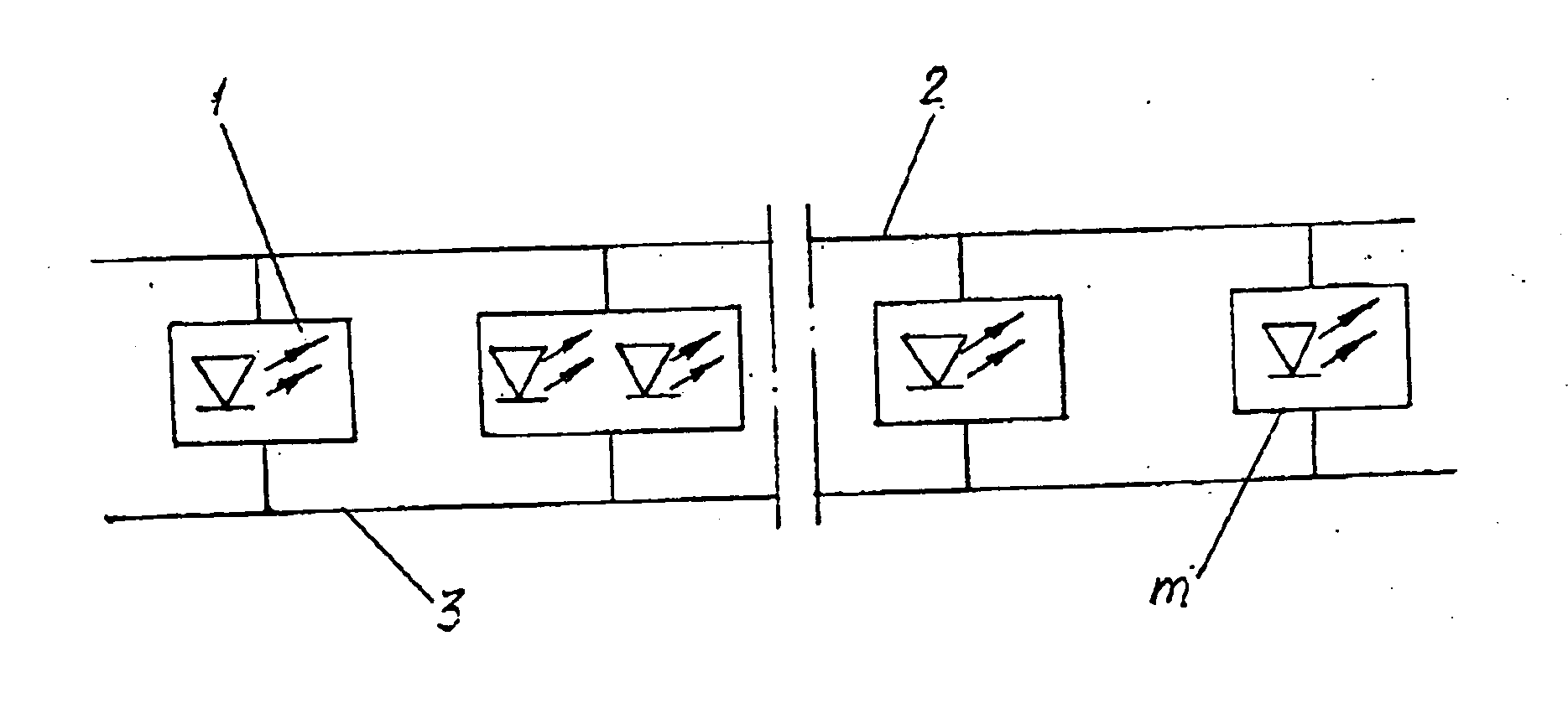
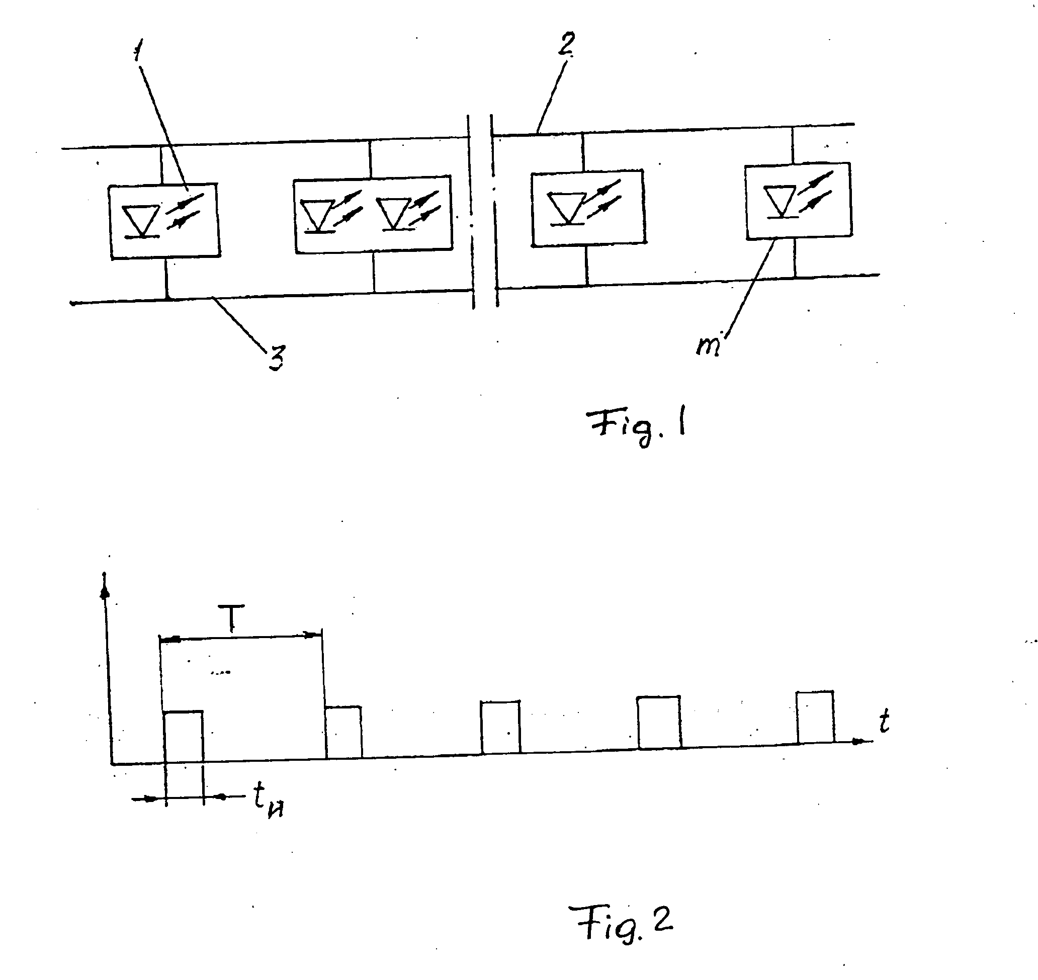
[0053] Each microprocessor operates in accordance with the cycle so as to provide change of brightness and color in a given concrete location in accordance with an individual program, and all of them provide a common light-dynamic effect.

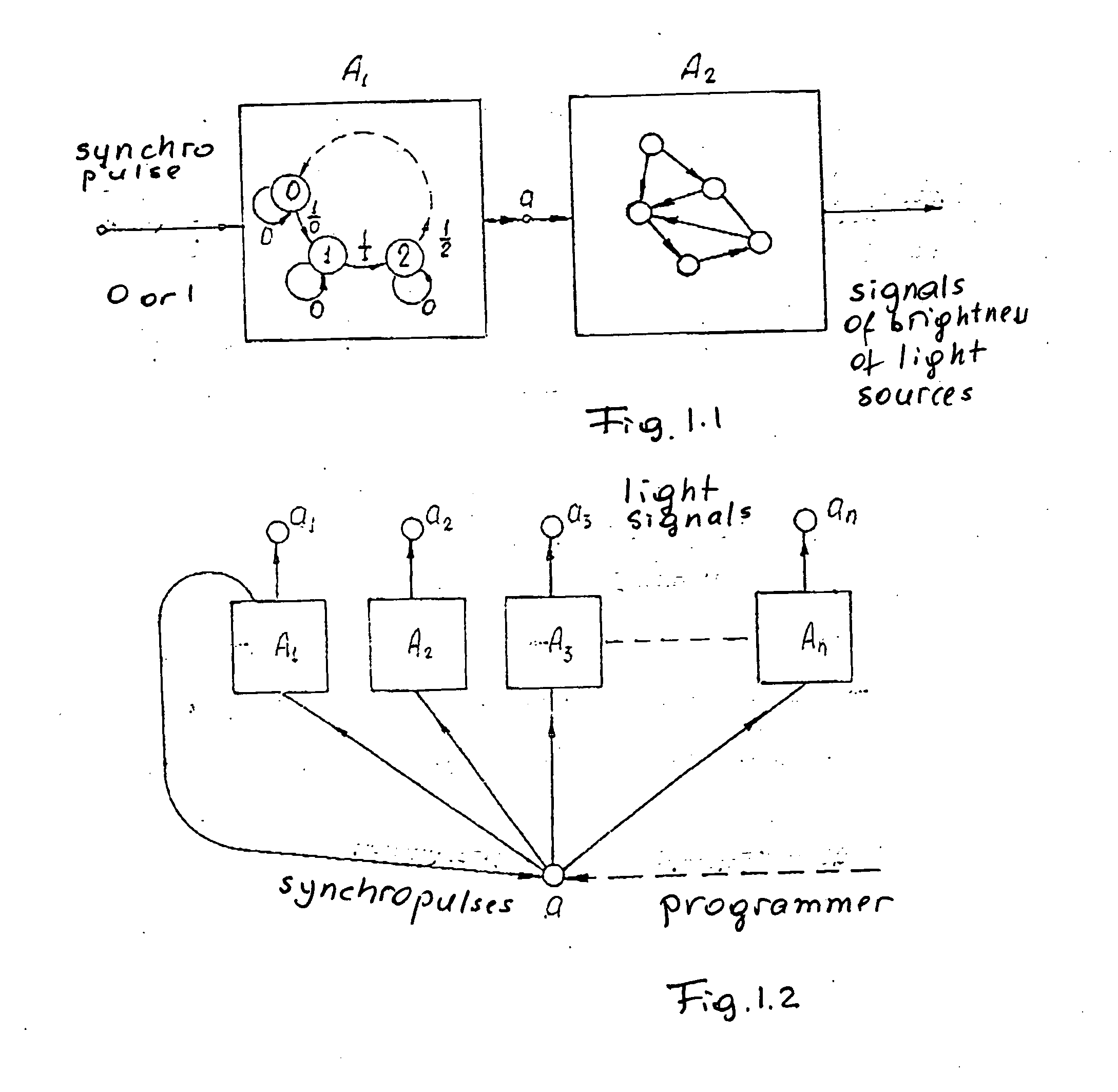
[0054] One module can be represented as a unity of two automatic elements as shown in FIG. 1.1. One of them operates as a counter of conditions 0, 1, 2 . . . in response to the supplied synchro pulse (input signal I). The synchro pulse generates one of its modules, by supplying it to the electric bus.

[0055] Therefore the automatic element A1 operates in accordance with the cycle A1. Physically, it is simply one register with zeroing after reaching the condition with the maximum number. A number of its condition represents the output signal of the automatic element A1. This signal is an input signal for the automatic element A2. The automatic element A2 is more complicated. Each of its conditions corresponds to a predetermined cond...

example 2

Illumination of Windows

[0063] For creating an original light-dynamic effect, conventional windows are utilized. For this purpose a light-dispersing image 29 is applied on one or several glasses 28, and a device for introduction of light into the glass is provided. Modular lines 30 of light sources are further provided. All lines are connected with one another by a single electrical bus shown in FIG. 1.3. Since all modules of each line on each window operate in accordance with coordinated programs, it is possible to create a single light-dynamic effect for all illuminated windows.

[0064] When the applied image is changed and applied on neighboring windows, new windows are supplied with additional lines of light sources, which are also connected to the electrical bus. Because of the change of the images and configuration of the system (additional windows) it is necessary to change the program of the light-dynamic effects. Then, all elements which are described in the Example 1 are ma...

example 3

Two-Coordinate Illumination

[0066] The lines 31 of the light sources are assembled into two-coordinate screens shown in FIG. 1.4. Similarly to other cases where the line with a great number of light modules with light sources is utilized, the frequency modulation significantly reduces requirements to electronic circuits. By means of such a “screen”, any image applied to the light-dispersing surface can be illuminated from the front, or the image which is assembled from colored light-dispersing elements can be illuminated as well. The device is substantially analogous to the so-called light-boxes, in which between two matted surfaces with the applied images, an elongated (non-pointed) static light source is arranged. The screen based on the modular lines differs from the light boxes in that it allows to create dynamic two-dimensional light effects. Because of this and because of the advantages of the modular programming devices described herein above, a wide area is provided for desi...


PUM


Abstract

A device for dynamic illumination has groups of light sources, a power supply source, each of the groups of light sources is formed as a light-emitting module which includes light diodes selected from the group consisting of one light diode and several light diodes, electronic keys corresponding to the light diodes for power supply of the light diodes through ballast resistors, a processor containing control programs for controlling brightness and color of the light diodes in time with the use of a method of frequency-pulse modulation, for controlling the electronic keys and interaction of the processors including synchronization of their operation, the modules having inputs which are electrically connected with one another and outputs which are grounded, wherein the modules are united in three-dimensional structures.

Description

BACKGROUND OF THE INVENTION [0001] The present invention relates to special areas of electrical technology and in particular to devices for light sources with control circuits and can be used with various advertising and demonstrating means with special effects, to provide visually observed three dimensional color images with unusual light effects, which create a special decorative effect in form of dynamically changed colorful decorative-art and advertising images, which are reproduced in volumes and on surfaces. [0002] Devices of this type are known, for example switching devices of light-diode and lamp garland which have groups of light sources forming garlands of different colors, a pulse generator which switches the garlands and formed with a conventional circuit including transistors, trinistors and invertors for a smooth turning on and turning off of the garlands, with the implementation of the effect of “running wave” (magazine RADIO number 11, 1983, pages 52-54). [0003] How...

Claims


Application Information

Patent Timeline
IPC IPC(8): G09G3/32
CPCH05B37/029Y02B20/346H05B33/0857H05B33/0818H05B33/0842H05B33/0803H05B45/20H05B47/155H05B45/335Y02B20/30H05B31/50
Inventor SINYUGIN, ANDREI V.GONCHARENKO, YURIY A.MARTINOV, YURIY I.SOUBBOTINE, GUENNADI
Owner SINYUGIN ANDREI V
Why Eureka
Try Eureka