
Method and apparatus for selecting a mip map level based on a min-axis value for texture mapping

a texture mapping and mip map technology, applied in the field of video graphics processing, can solve the problems of two sequential and interdependent rendering problems, poor texture cache coherency, and increased graphics display requirements of the system

Active Publication Date: 2007-08-09
ATI TECH INC
View PDF14 Cites 18 Cited by
  • Summary
  • Abstract
  • Description
  • Claims
  • Application Information

AI Technical Summary

Problems solved by technology

As computing systems continue to evolve, the graphical display requirements of the systems become more demanding.
In shadow mapping, adequate sampling of the shadow map poses two sequential and interdependent rendering problems.
Because the scene complexity may vary, the use of a single shadow map sampled at one sampling rate may result in using various texel-to-pixel ratios for different portions of the screen.
When rasterizing portions of the scene where the shadow map is in minification mode, the memory access pattern within the texture is fairly sparse, i.e., the memory access pattern is not localized in a small region in a texture, resulting in poor texture cache coherency.
Put another way, because a region in the shadow map may map to several different regions of the scene, the number of memory accesses is large and certain regions of the texture may be accessed several times with each access possibly causing a cache miss.
Filtering a shadow map, however, is not beneficial because taking the average of a texel's four parent texels biases at least one texel of the shadow map toward the light source.
While aliasing is reduced, the rendered image may appear blurred due to the manner in which mip map chains are constructed as downsampled versions of the original main texture.
However, in the case of anisotropic filtering, the number of mip map levels above the max-axis selected level is limited by the number of texture samples taken in the anisotropic filters since aliasing artifacts remain an issue due to the nature of the anisotropic filtering algorithm.
In the context of shadow mapping, however, neither selection scheme adequately reduces the number of artifacts in the rendered image.
Thus, when applying a shadow map to a surface or primitive, aliasing artifacts result where a single texel maps to several screen pixels.

Method used


Image

  • Method and apparatus for selecting a mip map level based on a min-axis value for texture mapping
  • Method and apparatus for selecting a mip map level based on a min-axis value for texture mapping
  • Method and apparatus for selecting a mip map level based on a min-axis value for texture mapping

Examples


Embodiment Construction

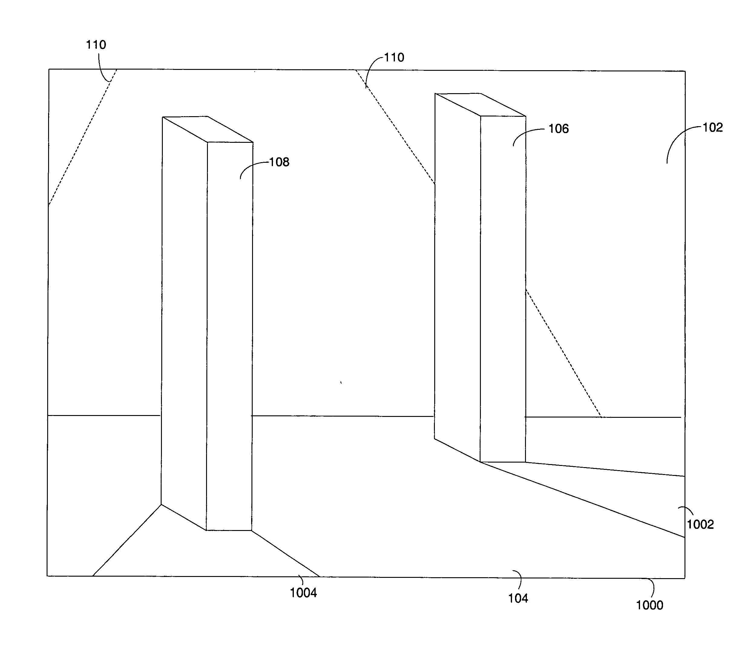
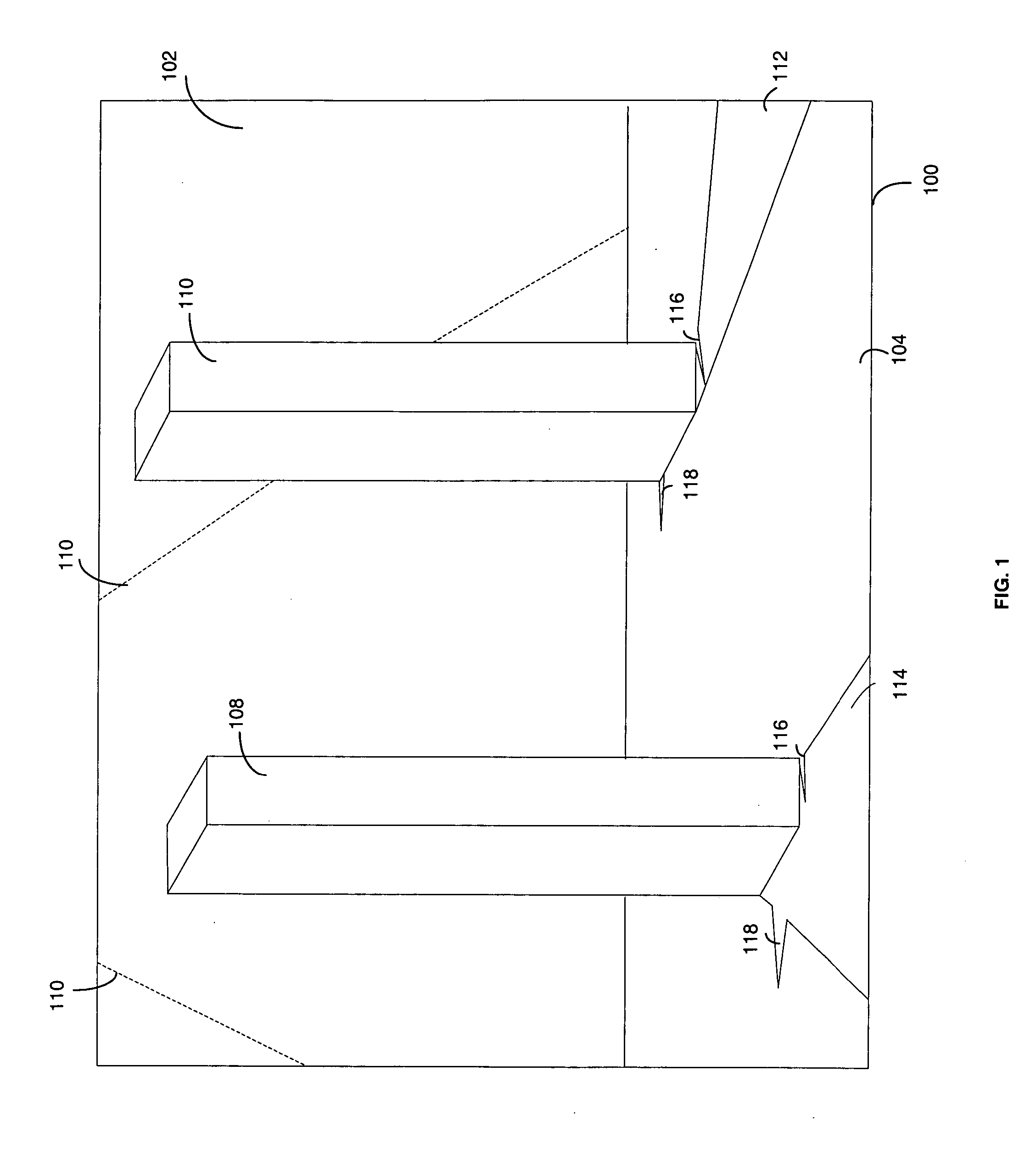
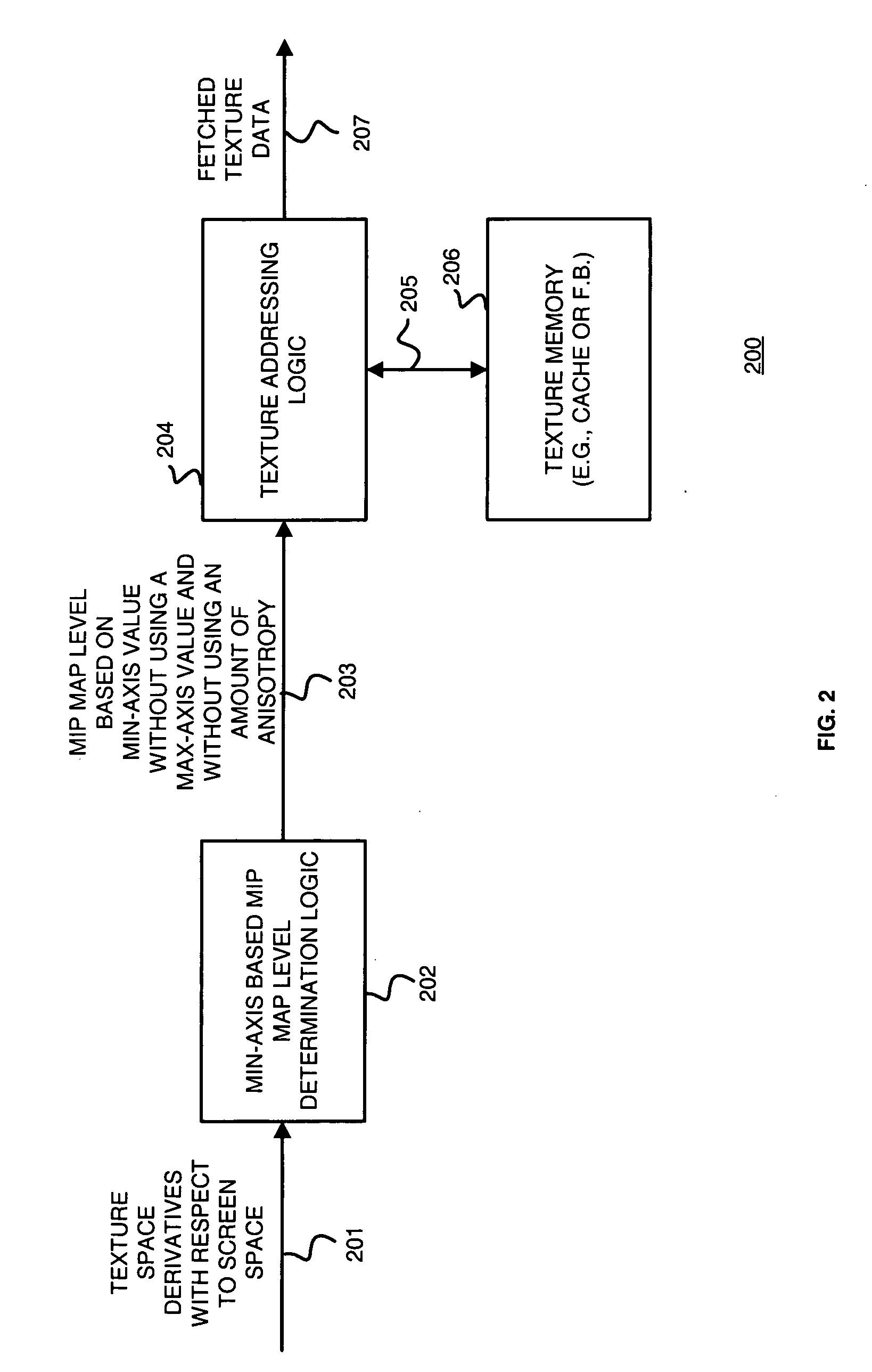
[0027] Generally, the present disclosure provides a method and apparatus for selecting a mip map level based on a min-axis level for use in texture mapping. In one embodiment, min-axis based mip map level determination logic receives a plurality of texture space derivatives with respect to screen space, such as du / dx, dv / dx, du / dy and dv / dy, and responsively selects a mip map level from a plurality of mip map levels, for instance in a mip map chain. The selected mip map level is based on a min-axis value without using a max-axis value and without using an amount of anisotropy. As provided in the background, no prior art mip map level selection scheme solely used a min-axis value to determine the desired mip map level. Thus, as indicated in FIG. 1, the images rendered using such schemes inadequately prevented aliased artifacts.

[0028] In one embodiment, selection of a mip map level based on a min-axis value may correspond to identifying the min-axis using the plurality of texture spa...


PUM


Abstract

Min-axis based mip map determination logic receives a plurality of texture space derivatives with respect to screen space for a given pixel and texel location and selects from a plurality of mip map levels a mip map level based on a min-axis without using a max-axis value and without using an amount of anisotropy. The plurality of mip map levels corresponds to mip map levels of a mip chain. The min-axis may be identified as the squares of the texture space derivatives with respect to either the x-axis or the y-axis of screen space. Selecting the mip map level based on the min-axis ensures that each texel of the selected mip map never maps to more than one pixel during texture mapping where the main texture is of sufficient resolution. Thus, using the mip map level based on the min-axis to fetch texture data from memory and render images results in few aliasing artifacts.

Description

FIELD OF THE INVENTION [0001] The invention generally relates to video graphics processing and more particularly to selecting a mip map level based on a min-axis value for texture mapping in a three-dimensional video graphics system. BACKGROUND OF THE INVENTION [0002] Computers are used in many applications. As computing systems continue to evolve, the graphical display requirements of the systems become more demanding. This is especially true in applications where three-dimensional graphic displays must be updated quickly. One example of such an application is a computer game where movement and modification of background images may place great demands on the processing power of the computing system. [0003] In order to display some screen images, detailed textures are stored in memory. These textures are then filtered and adapted to map to structures or graphic primitives for subsequent display. An example is a brick pattern that can be mapped onto a wall structure. If the wall is e...

Claims


Application Information

Patent Timeline
IPC IPC(8): G09G5/00
CPCG06T15/04
Inventor ISIDORO, JOHN R.WEI, TIEN E.
Owner ATI TECH INC
Learn More