Control device for controlling an astronomical telescope and a method for controlling the same

a technology of control device and astronomical telescope, which is applied in the direction of program control, electric programme control, instruments, etc., can solve the problems of low calculation accuracy, inadequate tracking algorithm, and conventional automatic telescope controllers that calculate the tracking speed only relatively slowly

Inactive Publication Date: 2007-08-09
XU WEN +1
View PDF6 Cites 18 Cited by
  • Summary
  • Abstract
  • Description
  • Claims
  • Application Information

AI Technical Summary

Benefits of technology

[0009]This invention provides a control device for controlling an astronomical telescope comprising a power input interface, a master controller and a motor drive controller. In certain embodiments, the control device further comprises a power output inter

Problems solved by technology

Specifically, conventional automatic telescope controllers calculate the tracking speed only relatively slowly, have an inadequate tracking algorithm, and low calculation accuracy.
In addition, connections between the various elements of conventional controllers are complex and often proprietary rather than universal.
Moreover, conventional controllers are easily damaged if revered polarity power is connected.
Conventional controllers also use two-line LCD displays which are inadequate at displaying a variety of information.
With respect to observation of celestial bodies, conventional controllers do not allow for an easy setup and calibration, and generally rely on use

Method used


Image

  • Control device for controlling an astronomical telescope and a method for controlling the same
  • Control device for controlling an astronomical telescope and a method for controlling the same
  • Control device for controlling an astronomical telescope and a method for controlling the same

Examples


example 1

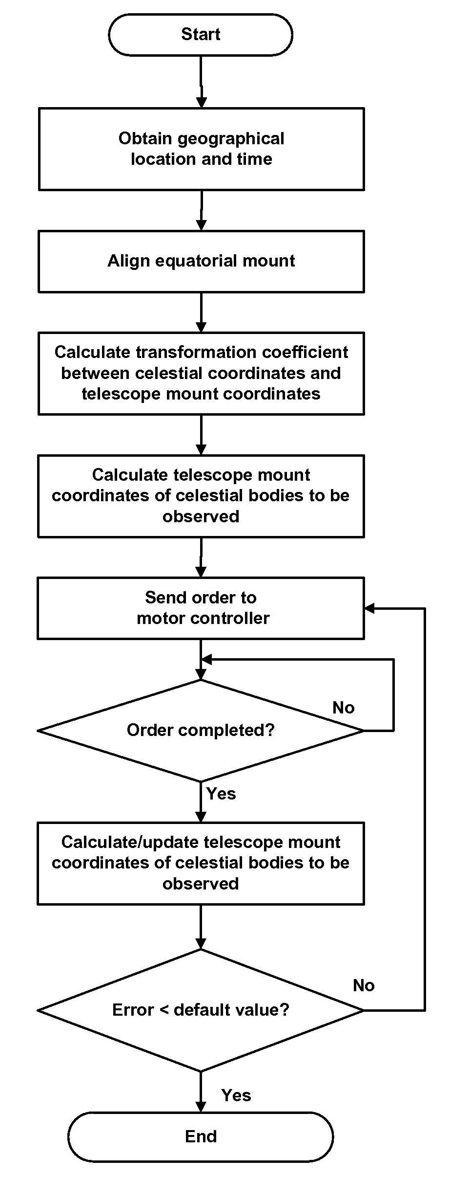
Calculating the Transforming Function Between Celestial Coordinates and Telescope Mount Position Coordinates

[0047]The equatorial coordinate of a first celestial body comprises the Right ascension=RA_S1 and the Declination=DEC_S1, and its coordinates in equatorial mount or theodolite comprise the Right ascension=RA_M1 and the Declination=DEC_M1. These coordinates are transformed to rectangular coordinates: X_S1, Y_S1, Z_S1 and X_M1, Y_M1, Z_M1, respectively. The equatorial coordinate of a second celestial body is Right ascension=RA_S2 and Declination=DEC_S2, and its coordinates in equatorial mount or theodolite is Right ascension=RA_M2 and Declination=DEC_M2. These coordinates are transformed to rectangular coordinates: X_S2, Y_S2, Z_S2 and X_M2, Y_M2, Z_M2, respectively.

[0048]Based on the rectangular coordinates of the two celestial bodies, a transformation matrix (T) and its inverse matrix (T)−1 (the transforming function) can be calculated, satisfying the following equations:

(X_S1...

example 2

Calculating Errors Between the Real Telescope Mount Position Coordinates and Their Calculated (Theoretical) Values

[0050]According to the original parameters, time, and geographical position of the celestial body, the equatorial coordinates that a celestial body would assume after a delay time of 1 second can be calculated.

[0051]Based on the expressions in Example 1, the coordinates, namely Right ascension=RA_M0 and Declination=DEC_M0, of the celestial body in the equatorial mount can be calculated. Since the coordinates recorded in the equatorial mount within the motor drive controller is Right ascension=RA_M1 and Declination =DEC_M1, the error can be calculated as follows:

[0052]The error of the right ascension=RA_M1−RA_M0.

[0053]The error of the declination=DEC_M1−DEC_M0.

[0054]The speed error of the right ascension=the error of the right ascension / 1 second.

[0055]The speed error of the declination=the error of the declination / 1 second.

[0056]The master controller repeats the above cal...


PUM


Abstract

This invention relates to a control device for controlling an astronomical telescope and, specifically, to a control device for automatic locating of celestial bodies, and to a method for controlling an astronomical telescope. The control device comprises a power input interface, a master controller, and an intelligent motor drive controller. The master controller comprises a CPU, an optional RAM, a FLASH microprocessor, one or more buttons, an LCD, a buzzer, one or more backlight diode lamps, one or more LED lights, a serial to USB interface, and an internal serial bus. The intelligent motor drive controller comprises a chip microprocessor having IAP functions, a two-way reversible PWM driving circuit having an output end and a detection end, a direct current motor, an optical encoder, an optical encoder detection circuit, and an over-current protection circuit. By calculating the coordinates of target bodies and converting them to equatorial mount coordinates, the microprocessor in the intelligent motor controller controls the motor to run, realizing the tracking of target celestial bodies.

Description

CROSS-REFERENCE TO RELATED APPLICATIONS[0001]This application claims priority to the Chinese Patent Application No. 200610038199.2 filed Feb. 9, 2006, the contents of which are incorporated herein by reference.BACKGROUND OF THE INVENTION[0002]1. Field of the Invention[0003]This invention relates to a control device for controlling an astronomical telescope and, specifically, to a control device for automatic locating of celestial bodies, and to a method for controlling an astronomical telescope.[0004]2. Description of the Related Art[0005]There are automatic telescope controllers known in the art. However, they have many shortcomings. Specifically, conventional automatic telescope controllers calculate the tracking speed only relatively slowly, have an inadequate tracking algorithm, and low calculation accuracy. In addition, connections between the various elements of conventional controllers are complex and often proprietary rather than universal. Conventional controllers also requ...

Claims


Application Information

Patent Timeline
IPC IPC(8): G02B23/00G01S19/07G01S19/05
CPCG02B23/16G02B23/02
Inventor XU, WENXU, NING
Owner XU WEN
Why Eureka
Try Eureka