
All-in-one LED assembly, string assembly and method

a technology of led strings and assembly methods, applied in the direction of lighting and heating apparatus, coupling device connections, decorative arts, etc., can solve the problems of loss of materials and quality, high cost of injection molding machines, and individual led lamps susceptible to th

Inactive Publication Date: 2007-08-09
YU JING JING
View PDF13 Cites 36 Cited by
  • Summary
  • Abstract
  • Description
  • Claims
  • Application Information

AI Technical Summary

Problems solved by technology

However, all the current packaging assemblies for separable LED strings have drawbacks because the ability to remove the LED makes the individual LED lamps susceptible to theft especially when the LED stings are placed in public areas.
When manufactured, each LED lamp is individually packaged onto a string using injection molding technology and thus has much higher cost associated with the injection molding machines, dies and the necessity to do final assembly of the components at the injection molding machine.
Moreover, the current manufacture procedure often damages the LED pins and diode bodies causing loss of materials and quality problems.

Method used


Image

  • All-in-one LED assembly, string assembly and method
  • All-in-one LED assembly, string assembly and method
  • All-in-one LED assembly, string assembly and method

Examples


first embodiment

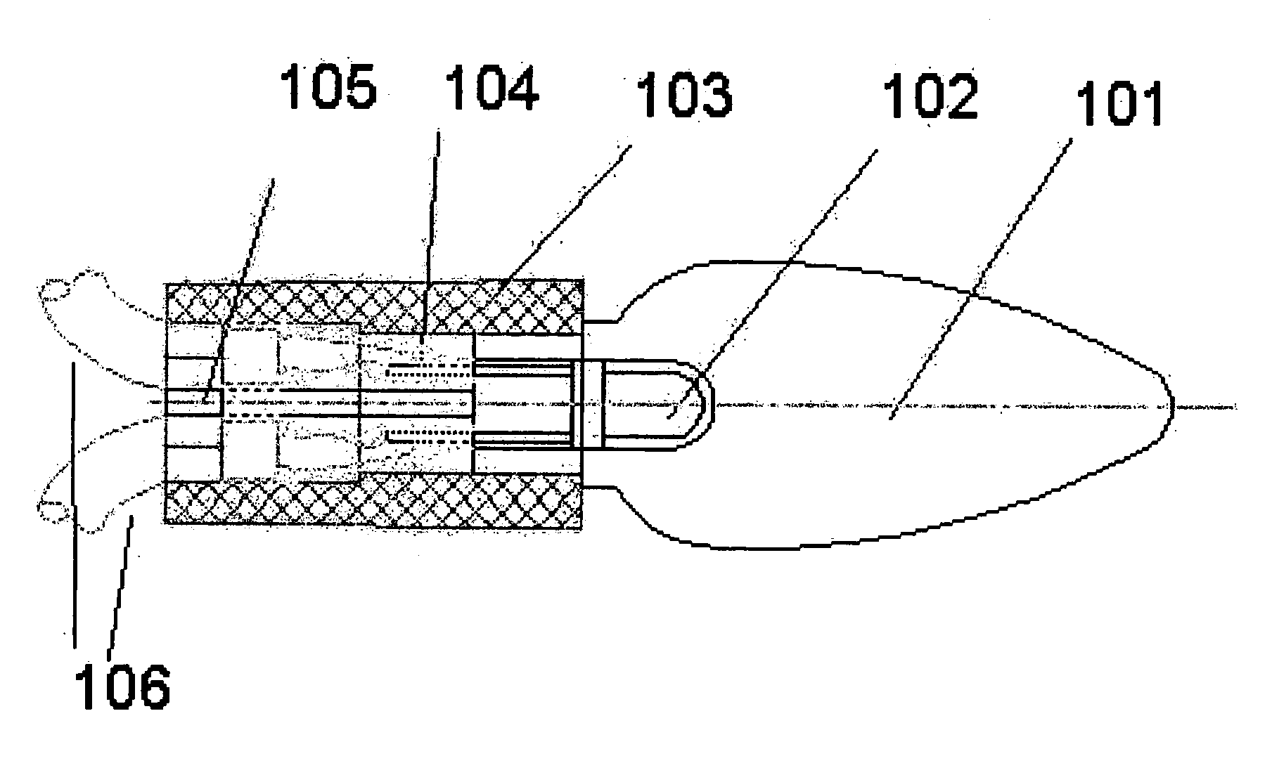
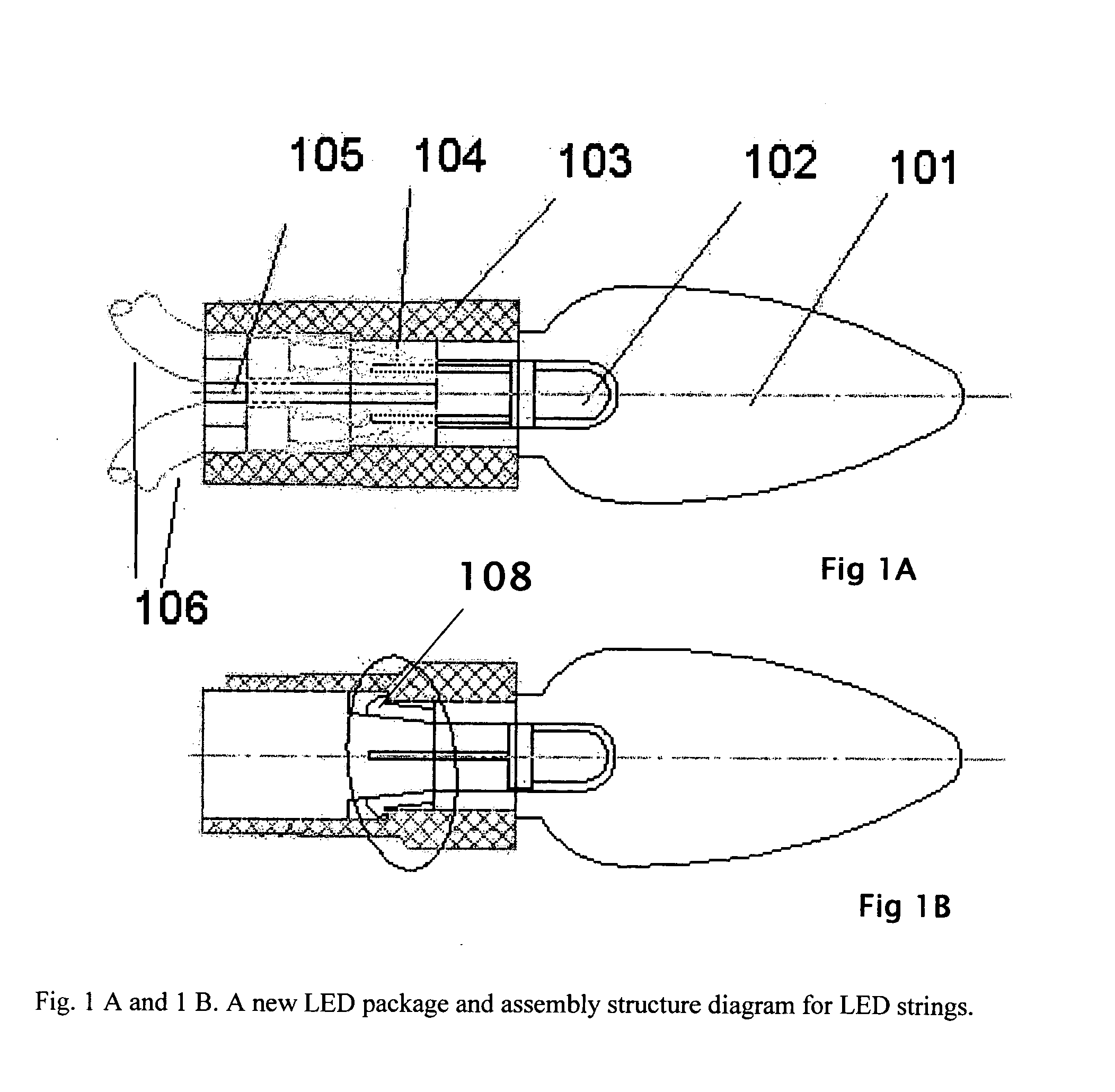
[0012] The plug fits around the electrical wires 106 and any insulation and when assembled does not interfere or damage the electrical connection of the LED pins and their respective electrical wires. In the first embodiment, in order to facilitate assembly of the plug around the wires 106, before it is inserted into the bottom opening of the lamp holder, the illustrated embodiment of the plug has a break or cut extending from the outer perimeter toward the axial center area or other desired area of the plug where the wires will be positioned. This break or cut 110 may be radial, jagged or spiral and allows the plug to be easily fitted around the wires 106, as a ring, with the wires passing through the plug from one end to the other end. Before insertion of the plug into the bottom opening, the plug in its position around the wires is moved along the wires toward the electrical connections with the pins and into the bottom opening of the lamp holder. The use of the cut or break 110 ...

third embodiment

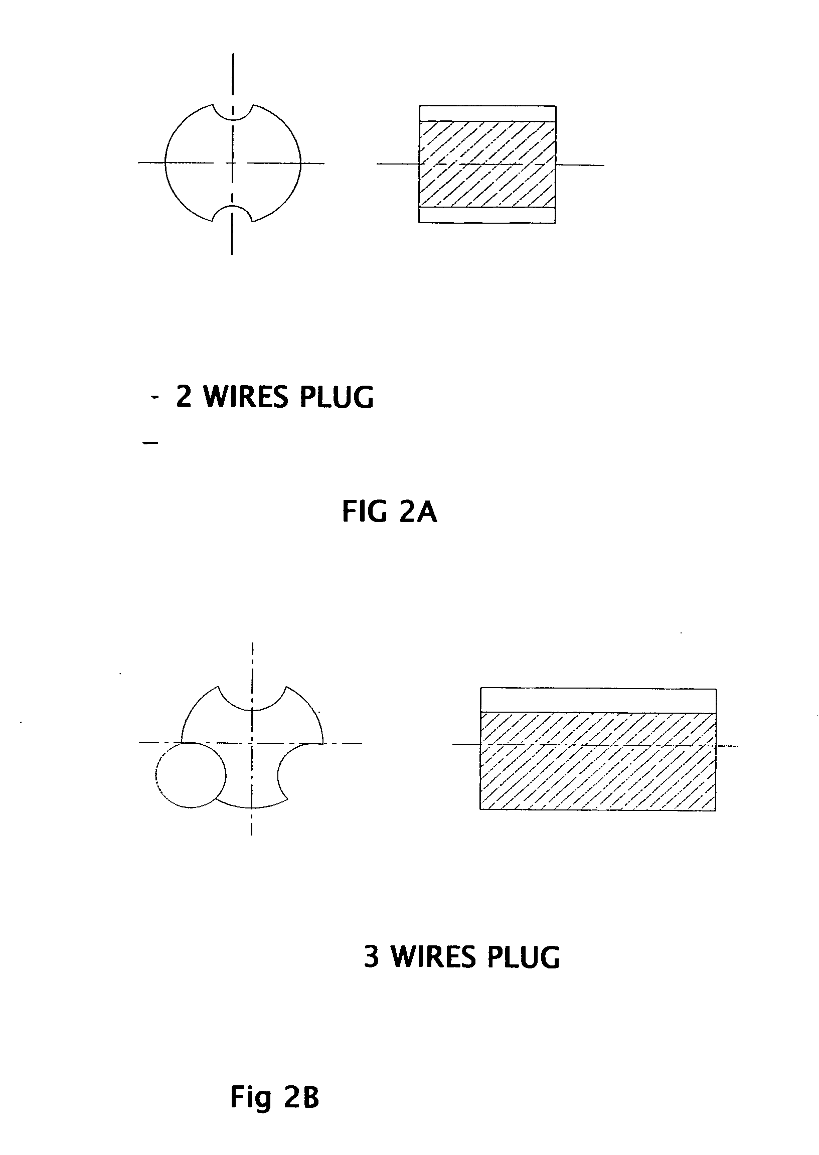
[0013] In a third embodiment, such as illustrated in FIGS. 3A and B and FIGS. 4A and B, if there is no cut or break to allow the plug to be fitted around the wires 106, the wires must be fed through the passageways in the plug before the wires are connected to the LED pins.

[0014] In the first embodiment, because the plug 105 is elastic and its diameter is slightly larger than the diameter of the bottom opening into which it is forced, the plug is deformed and compressed by the sides of the bottom opening of the lamp holder and thereby compression seals the break or cut 110 through which the plug was placed around the wires and also forms a seal around the wires and any associated insulation. Thus the plug operates to force the clip 108 to be tightly engaged with lamp holder 103. In addition the plug supports the wires and their connections with the pins.

[0015] Another alternative assembly uses a plug made of epoxy, clay, plastic, or similar material or combination known in the arts...


PUM


Abstract

The invention presents a new practical LED assembly and LED string assembly. The invented LED package includes an LED, a lamp cover, a lamp holder, wire connections, and a plug. The LED with its electrical connections is inserted and positioned in the lamp cover / lamp holder subassembly. The bottom opening of the lamp holder and the exit path of the wires are sealed by a plug. Compared to the conventional LED string manufacture procedures using injection modeling, the new assembly uses discrete components that make the LED assembly components standardized and replaceable, and dramatically reduce production cost and improve manufacture efficiency. Because the new assembly structure is tightly attached and hence discouraging any unauthorized removal of the expensive LED lamps from the strings.

Description

FIELD OF THE INVENTION [0001] The present invention relates to the field of decorative lighting and, more particularly, to light emitting diode (LED) assemblies and LED strings and the method of assembly. Heading DESCRIPTION OF RELATED ART [0002] Semiconductor Light emitting diodes (LED) have been widely used as decorative lighting sources, especially on holidays because of their low cost and perfect physical properties including their low operating voltage and power, small sizes, long lifetime and great stability. LEDs are cool light sources without generating heat and thus can operate for long periods of daily operation. [0003] There are two types of lamps used in conventional LED strings: separable lamps and inseparable lamps. In the first type, a LED lamp can be plugged into and unplugged from a string, thus is replaceable. Separable LED lamps can be manufactured separately from the rest of the string and thus allow flexibility in production and assembly. However, all the curren...

Claims


Application Information

Patent Timeline
IPC IPC(8): F21S13/14
CPCF21S4/001F21V3/00F21V17/06H01R33/09F21W2121/00F21Y2101/02H01R13/506F21V19/0005F21S4/10F21Y2115/10
Inventor YU, JING JING
Owner YU JING JING
Features
  • Generate Ideas
  • Intellectual Property
  • Life Sciences
  • Materials
  • Tech Scout
  • Unparalleled Data Quality
  • Higher Quality Content
  • 60% Fewer Hallucinations
Learn More