
Connection system, in particular a plug-in connection system for the transmission of data and power supply signals

a technology of data transmission and power supply signal, which is applied in the direction of transmission system, coupling device connection, transmission, etc., can solve the problems of general inability of process operators to discern on site, and achieve the effects of low power consumption, simple connection construction and high security

Active Publication Date: 2007-08-09
KNICK ELEKTRONISCHE MESSGERATE
View PDF7 Cites 6 Cited by
  • Summary
  • Abstract
  • Description
  • Claims
  • Application Information

AI Technical Summary

Benefits of technology

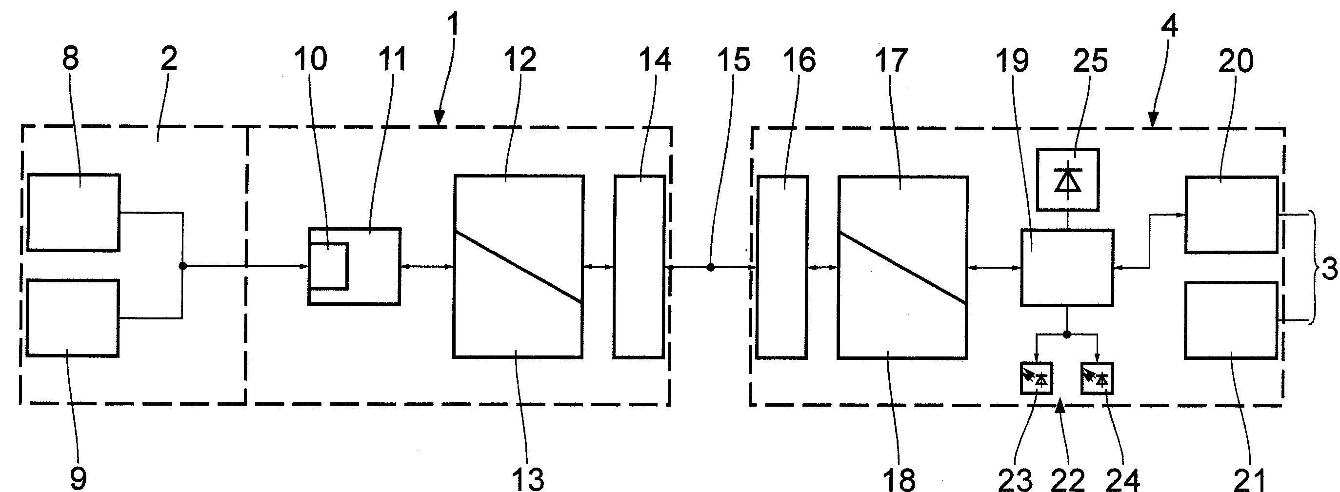
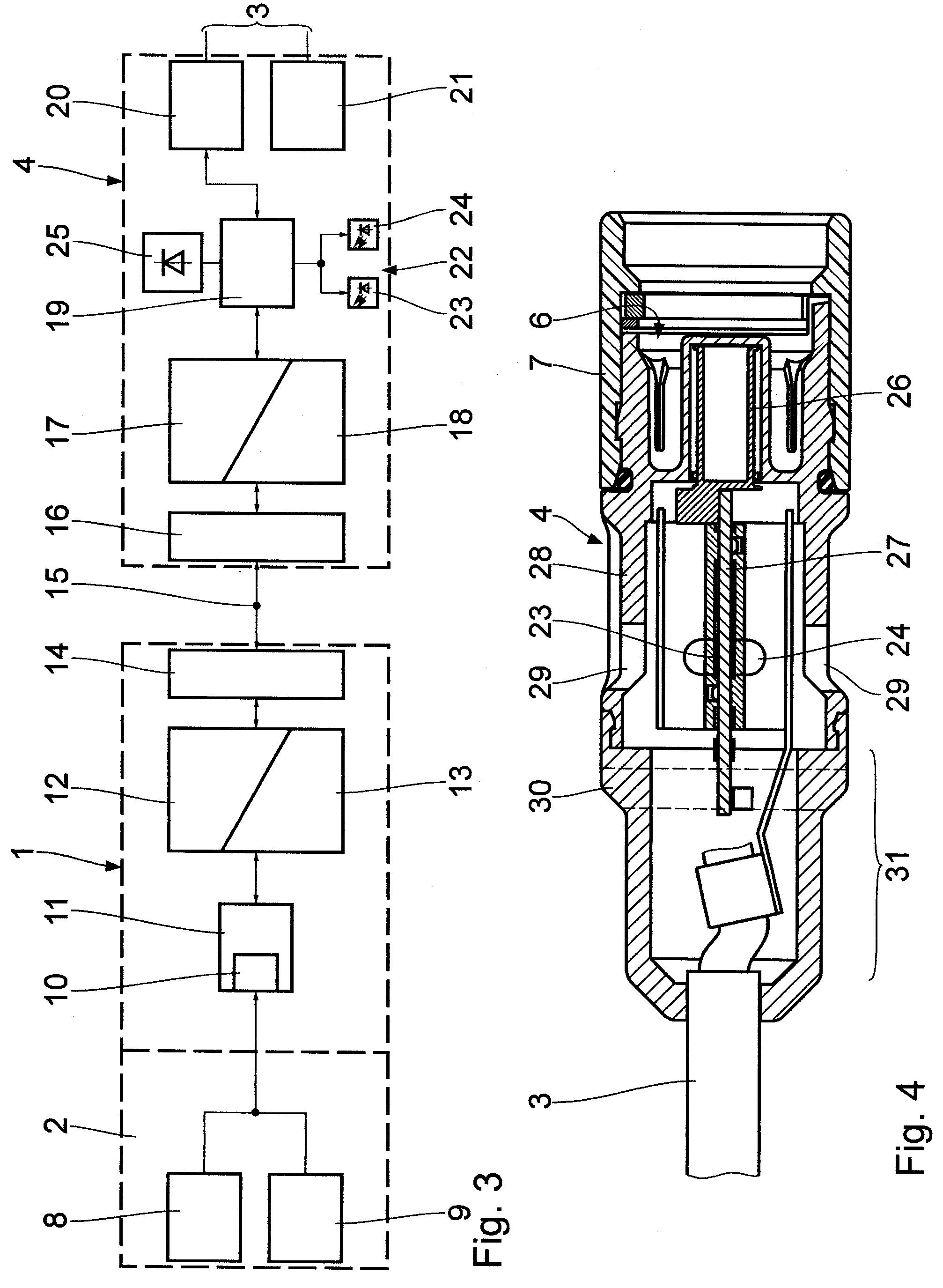
"The invention is a connection system that includes a sensor-side connection element with a power signal receiver, a data modulator / demodulator unit, a data interface, a primary power supply, and a microprocessor-assisted control and memory unit. The system also includes an optical diagnosis display unit that can display defined state parameters of the measuring and transmission system. The optical diagnosis display unit can display the voltage supply state, data transmission behavior, and the state of the sensor of the measuring and transmission system. The system can also be equipped with an interface for wireless communication of data to a separate entity and a window for easy visual inspection of the connection system. The technical effects of the invention include improved monitoring and diagnosis of the sensor and transmission system, convenient and secure data transmission, and user-friendly visual inspection of the connection system."

Problems solved by technology

This gives rise to the problem that it is generally not possible for the process operators to discern on site at a measuring point whether the plug-in connection system is operating optimally, in particular whether the measuring and transmission system is in an appropriate operating state for the measurement variables to be picked off.

Method used


Image

  • Connection system, in particular a plug-in connection system for the transmission of data and power supply signals
  • Connection system, in particular a plug-in connection system for the transmission of data and power supply signals
  • Connection system, in particular a plug-in connection system for the transmission of data and power supply signals

Examples


Embodiment Construction

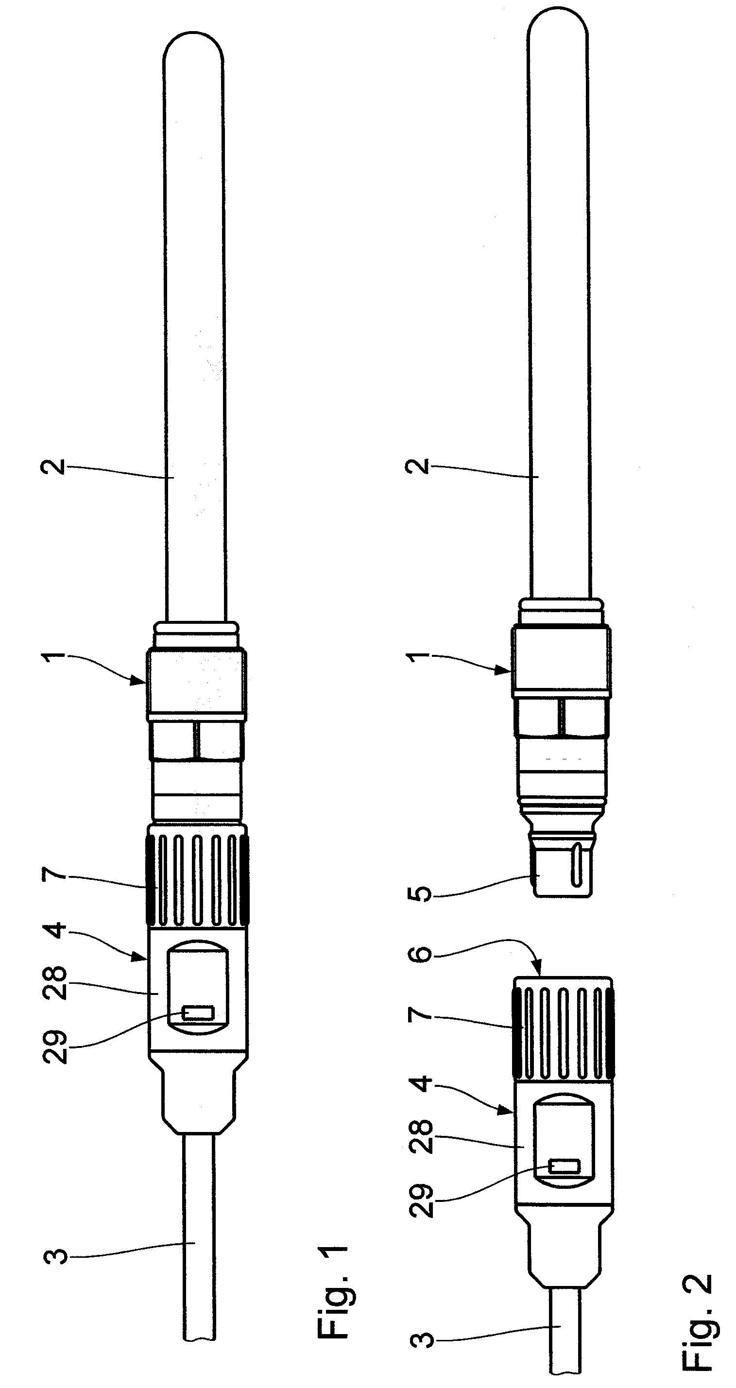
[0020]The plug-in connection system shown in FIGS. 1 and 2 comprises a sensor-side plug element 1 to which there is directly fastened a sensor means 2 shown schematically in the present case to be tubular. This means may, for example, be a pH probe comprising a temperature detection means, but also any other type of sensor such as, for example, an oxygen or conductivity probe. The sensor means 2 is positioned in this case in the process to be monitored. In order to forward the measurement data to a corresponding base unit, such as for example a field bus device, a data and supply line 3 is linked to the field bus device via the plug-in connection system according to the invention. The data line could in this case also be in the form of a two-wire bus line. The socket element 4, which comprises a recess 6, the shape of which is adapted to the plug-in portion 5 of the plug element 1, for mechanical and inductive coupling between the plug element 1 and socket element 2, cooperates in t...


PUM


Abstract

A connection system for the preferably contactless transmission of data and power supply signals between a sensor means and a base unit in a measuring and transmission system comprises a sensor-side and a base-side connection element. There is provided in at least one of the connection elements an optical diagnosis display unit for displaying state parameters within the measuring and transmission system.

Description

BACKGROUND OF THE INVENTION[0001]1. Field of the Invention[0002]The invention relates to a connection system, and in particular to a plug-in connection system for the preferably contactless transmission of data and power supply signals between a sensor means and a base unit in a measuring and transmission system. The term “connection system” as used in the present invention encompasses all possible coupling mechanisms which can be mechanically and electrically connected and isolated, plug connectors comprising a plug and socket element obviously being the most conventional examples of connectors of this type in electrical engineering. Such connectors may be configured in a directly contacting manner, but also in a contactless manner, for example inductively, capacitively or optically.[0003]2. Background Art[0004]The contactless transmission of switch signals and AC voltages in tele-communications and data transmission systems is known from DE 195 40 854 A1, for example, in the form ...

Claims


Application Information

Patent Timeline
Patent Type & Authority Applications(United States)
IPC IPC(8): H04J3/14
CPCH04L1/24H01F2038/143Y10S439/95
Inventor FEUCHT, WOLFGANGGIEBSON, JORG
Owner KNICK ELEKTRONISCHE MESSGERATE
Learn More