Method and apparatus for selectively applying interference cancellation in spread spectrum systems

a spread spectrum and interference cancellation technology, applied in the direction of amplitude demodulation, line-fault/interference reduction, pulse technique, etc., can solve the problems of reducing and affecting the signal quality of the communication channel. , to achieve the effect of increasing the strength of the desired signal

Active Publication Date: 2007-08-09
III HLDG 1
View PDF99 Cites 195 Cited by
  • Summary
  • Abstract
  • Description
  • Claims
  • Application Information

AI Technical Summary

Benefits of technology

[0009] If an increase in the signal to noise ratio of a desired signal path is not detected, the interference canceled signal stream will not be provided to a demodulation finger assigned to that desired signal path. In accordance with another embodiment of the present invention, an interference canceled signal stream is not provided to a demodulation finger assigned to a desired signal path unless it has been determined that the interference canceled signal stream will likely result in an increase in the strength of the desired signal by at least a threshold amount. In accordance with embodiments of the present invention, the analysis of the effect of providing different interference canceled signals to demodulation fingers can proceed such that either the raw signal stream or an interference canceled signal stream is identified as providing the greatest signal strength with respect to a desired signal path. This can be done for each signal path assigned to a demodulating finger provided by a receiver. In accordance with another embodiment of the present invention, signal cancellation may be achieved using various methods. For example, a replica of the potential interferer or identified interferer may be subtracted from the raw signal stream. In accordance with another embodiment of the present invention, serial cancellation techniques using projection-based methods of removing potential interferers or identified interferers may be used. In accordance with still other embodiments of the present invention, parallel cancellation of potential interferers and identified interferers may be applied.

Problems solved by technology

When a demodulation processor is tracking a particular signal path, signal paths associated with other transmitters appear to that processor as noise.
Because signal paths other than the signal path being tracked appear as noise to a demodulation processor, the signal to noise ratio with respect to a tracked or desired signal path can be low, which can result in a communication channel with poor quality and reliability.
In particular, signals from sources that are in close proximity to the receiver can drown out signals from sources that are farther away from the receiver.
Accordingly, because of this “near-far” problem, signal diversity is limited.
In addition to leaving communication channels more vulnerable to interruption, relatively weak signals that might otherwise be available to a receiver lie beneath the noise floor created in the environment by other relatively strong signals.
This limitation in acquiring and tracking signals from distant sources caused by the near-far problem also limits the effectiveness of location schemes that rely on triangulation techniques.
However, such schemes may be complex and difficult to implement.
In addition, where sources such as base stations are in communication with a large number of receivers, some of which are close to the source and others of which are far from the source, the limitation of signal power may not be feasible.
However, such systems have not provided for the flexible application of such cancellation.
As a result, the use of conventional interference cancellation schemes, as they have heretofore been applied, can actually result in poorer signal to noise ratios with respect to desired signal paths than if no interference cancellation had been applied.

Method used


Image

  • Method and apparatus for selectively applying interference cancellation in spread spectrum systems
  • Method and apparatus for selectively applying interference cancellation in spread spectrum systems
  • Method and apparatus for selectively applying interference cancellation in spread spectrum systems

Examples


Embodiment Construction

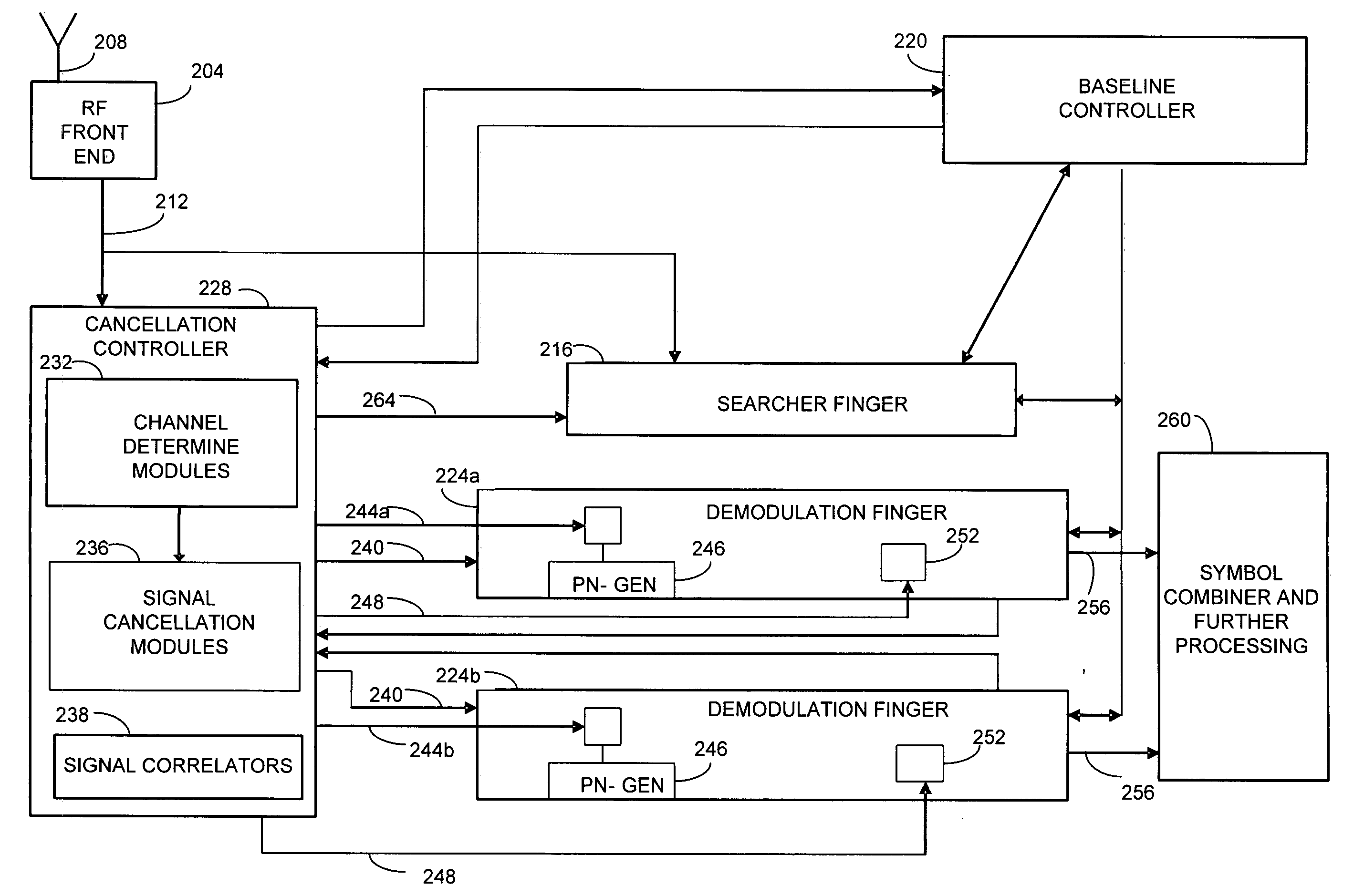
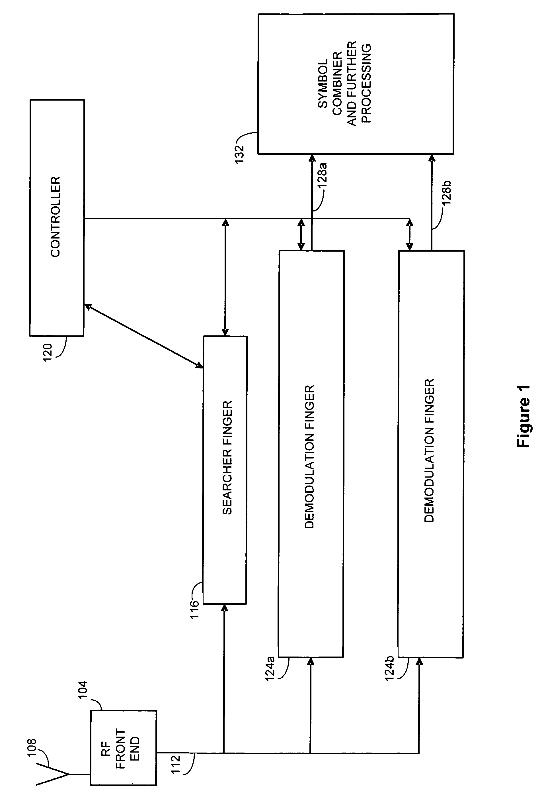
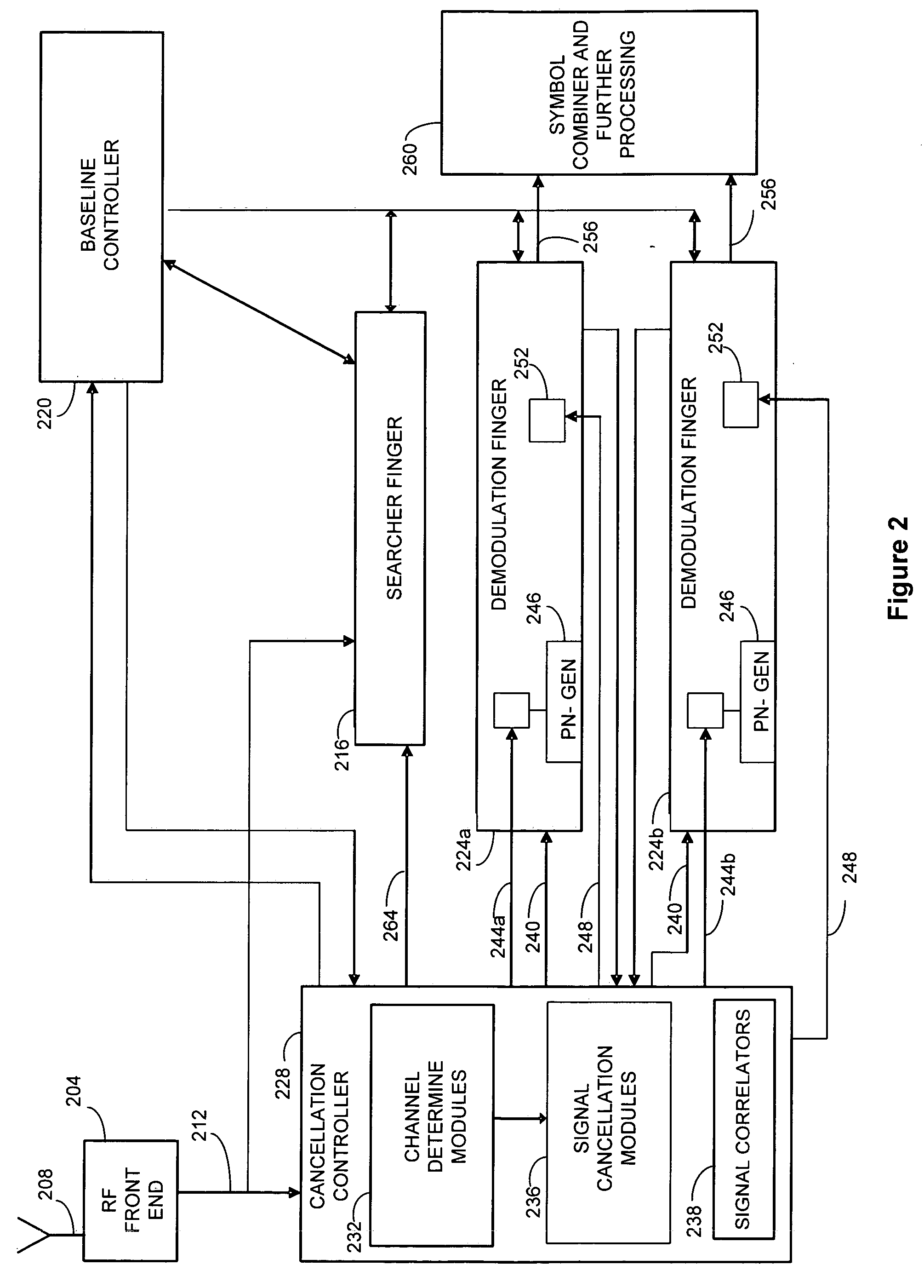
[0025] With reference now to FIG. 1, components of a baseline or prior art spread spectrum communication receiver 100 are illustrated. As depicted in FIG. 1, signals are provided to a radio frequency front end 104 by an antenna 108. In a typical environment, a number of different signals, for example, signals produced by different base stations, different sectors of a base station, or multi-path or reflected versions of the signals can be received at the radio frequency front end 104. As can be appreciated by one of skill in the art, signals from different base stations or different sectors of a base station are typically identified by an associated path number, which identifies the base station or base station and sector according to the time offset of the signal path. Multi-path versions of signals are identified by the path number of the line of sight version of the signal, plus an additional time offset to account for the longer path followed by the reflected signal. As can furt...


PUM


Abstract

The present invention is directed to the selective provision of interference canceled signal streams to demodulating fingers in a communication receiver. According to the present invention, potential interferer signal paths are identified. Signal streams having one or more potential interferer signals removed or canceled are created, and a correlation is performed to determine whether the strength of a desired signal path increased as a result. If the correlation indicates that the strength of a desired signal path was increased by the signal cancellation, the interference canceled signal stream is provided to the demodulation finger assigned to track the desired signal path. If the correlation determines that the strength of the desired signal path did not increase as a result of performing interference cancellation, the raw or a different interference canceled signal stream is provided to the demodulation finger.

Description

CROSS-REFERENCED TO RELATED APPLICATIONS [0001] This application claims the benefit of U.S. Provisional Application No. 60 / 412,550, entitled “Controller For Interference Cancellation and Spread Spectrum Systems,” filed Sep. 23, 2002, the entire disclosure of which is hereby incorporated by reference.FIELD OF THE INVENTION [0002] The present invention is directed to the application of interference cancellation in spread spectrum systems. In particular, the present invention is directed to selectively applying interference cancellation such that if interference cancellation has resulted in an improved signal, interference cancellation can be used or continued. BACKGROUND OF THE INVENTION [0003] Wireless communication systems should provide for a large number of secure (or private) communication channels within their allotted frequency space. In order to achieve these goals, spread spectrum systems have been developed. In a spread spectrum type system, spreading codes are used that all...

Claims


Application Information

Patent Timeline
Patent Type & Authority Applications(United States)
IPC IPC(8): H04B1/00H03D1/04H04B1/707
CPCH04B1/7107H04B1/71072H04B2001/71077H04B1/7117H04B1/7115
Inventor NARAYAN, ANAND P.OLSON, ERIC S.JAIN, PRASHANT
Owner III HLDG 1
Why Eureka
Try Eureka