
Fuel supply device for internal combustion engine and control method therefor

a technology of internal combustion engine and fuel supply device, which is applied in the direction of combustion-air/fuel-air treatment, instruments, physical/chemical process catalysts, etc., can solve the problems of not being able to generate only high-octane-number fuel, adversely affecting the stability of combustion,

Inactive Publication Date: 2007-08-09
NISSAN MOTOR CO LTD +1
View PDF4 Cites 14 Cited by
  • Summary
  • Abstract
  • Description
  • Claims
  • Application Information

AI Technical Summary

Benefits of technology

[0005] In the prior art device, the high-octane-number fuel is obtained as a by-product of the partial oxidation reforming reaction and the steam reforming reaction for extracting the reformate gas containing hydrogen and carbon monoxide. It is therefore not possible to generate only the high-octane-number fuel without causing a reforming reaction. As a result, the amount of the high-octane-number fuel may be less than required.

Problems solved by technology

It is therefore not possible to generate only the high-octane-number fuel without causing a reforming reaction.
Nitrogen is an agent that dilutes fuel, and hence adversely affects the stability of combustion.

Method used


Image

  • Fuel supply device for internal combustion engine and control method therefor
  • Fuel supply device for internal combustion engine and control method therefor
  • Fuel supply device for internal combustion engine and control method therefor

Examples


second embodiment

[0105] Next, referring to FIGS. 10 and 11, this invention will be described.

first embodiment

[0106] Referring to FIG. 10, this embodiment further comprises an electric heater 58 installed in the catalytic converter 5 in order to heat the reforming catalyst 6. The hardware constitution other than the heater 59 is identical to that of the

[0107] The electric heater 58 is activated under the criteria shown in FIG. 11.

[0108] Specifically, the electric heater 58 is activated in a low load engine condition in which the temperature of the reforming catalyst 6 does not rise promptly. In this condition, the heat generated by the electric heater 58 is used for heating the reforming catalyst 6 directly to raise the temperature thereof. The ECU 60 controls power supply to the electric heater 58 along with the temperature control of the reforming catalyst 6 through the execution of the fuel reforming control routine of FIG. 7.

[0109] To control the power supply to the electric heater 58, a heater power supply map having the characteristic shown in FIG. 11 is stored in the ROM of the ECU...

third embodiment

[0111] Next, referring to FIGS. 12 and 13, and FIGS. 14A and 14B, this invention will be described.

[0112] Referring to FIG. 13, according to this embodiment, the internal combustion engine 1 further comprises an auxiliary combustion chamber 50 in the cylinder head 40 adjacent to the combustion chamber 45 (hereinafter referred to as a main combustion chamber 45) in each cylinder.

[0113] The capacity of the auxiliary combustion chamber 50 is set smaller than that of the main combustion chamber. A spouting hole 52 formed in the cylinder head 40 connects the auxiliary combustion chamber 50 with the main combustion chamber 45.

[0114] The internal combustion engine 1 further comprises a second decomposed fuel injector 36 installed in the cylinder head 40 facing the auxiliary combustion chamber 50. The second decomposed fuel injector 36 injects the decomposed fuel in the decomposed fuel storage tank 21 into the auxiliary combustion chamber 50. Further, according to this embodiment, the spa...


PUM

PropertyMeasurementUnit
temperatureaaaaaaaaaa

Abstract

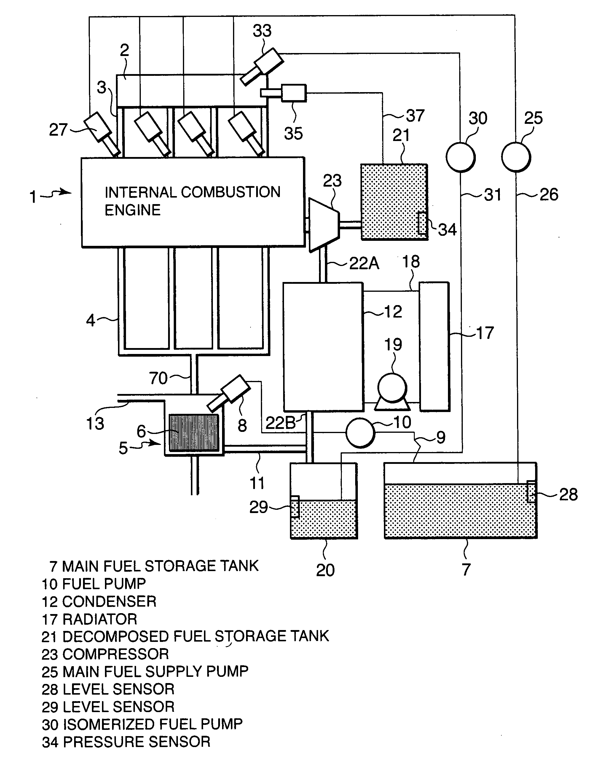
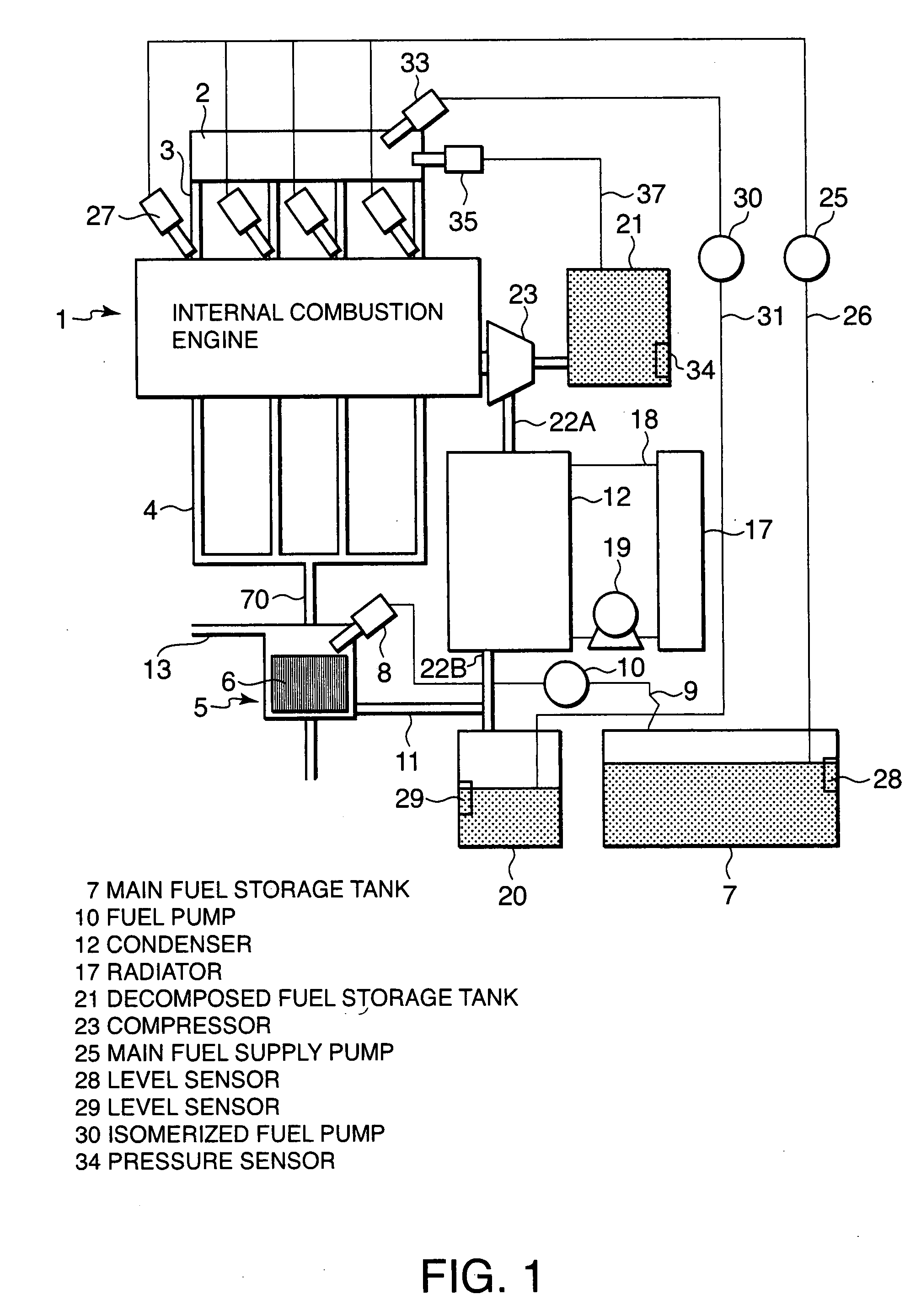
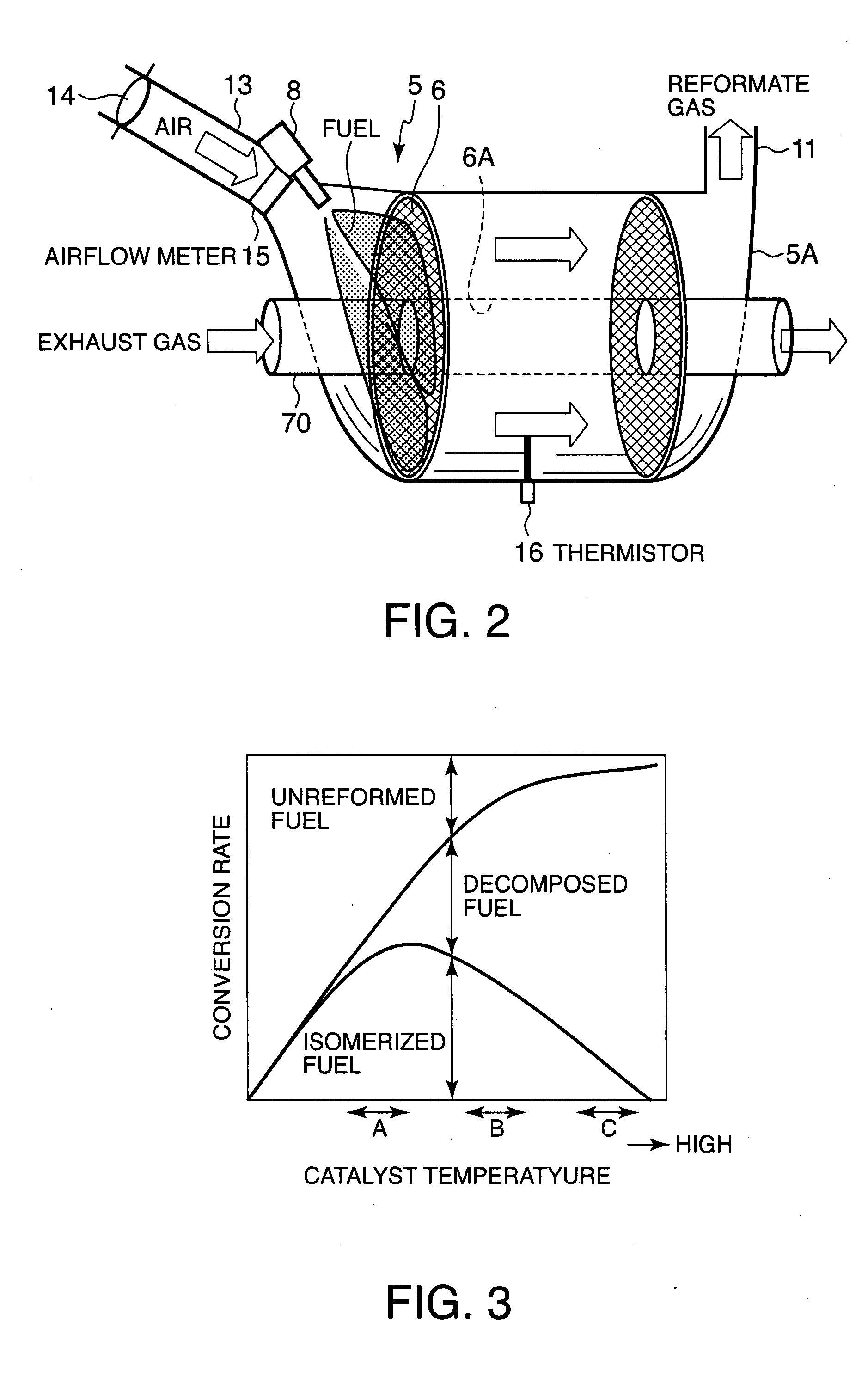
A reforming catalyst (6) induces an isomerization reforming reaction and a decomposition reforming reaction of a gasoline fuel. Injectors (27, 33, 35, 36) supply an isomerized fuel generated by the isomerization reforming reaction and a decomposed fuel generated by the decomposition reforming reaction respectively to the internal combustion engine (1). The ratio of the isomerization reforming reaction and the decomposition reforming reaction depends on a catalyst temperature, and can be altered arbitrarily by controlling an air supply amount to the catalyst (6) via an air amount regulating valve (14) and a fuel supply amount to the catalyst (6) via a fuel injector (8) and thereby controlling the catalyst temperature.

Description

FIELD OF THE INVENTION [0001] This invention relates to the reforming of a gasoline fuel supplied to an internal combustion engine. BACKGROUND OF THE INVENTION [0002] JP2000-291499A, published by the Japan Patent Office in 2000 proposes a fuel supply device which reforms a gasoline fuel before supplying it to an internal combustion engine. The device extracts a reformate gas containing hydrogen and carbon monoxide by causing a partial oxidation reforming reaction and a steam reforming reaction in the gasoline fuel. The residual fuel which has not undergone the reforming reaction is a high-octane-number fuel which has a relatively small molecular mass. [0003] The reformate gas has a high combustion speed and brings about an effect of ensuring that the ignition of a fuel-air mixture, and hence the stability of combustion, is enhanced in a state where the internal combustion engine performs a lean burn operation. [0004] In contrast, the high-octane-number fuel prevents knocking from oc...

Claims


Application Information

Patent Timeline
Patent Type & Authority Applications(United States)
IPC IPC(8): B01J8/02G05D23/00
CPCF02D19/08F02M25/12Y02T10/36Y02T10/121F02M27/02Y02T10/12Y02T10/30
Inventor HOTTA, ISAMUKUBO, MASAAKITAKAHASHI, EIJIASHIDA, KOICHISEKINE, YASUSHI
Owner NISSAN MOTOR CO LTD
Learn More