Joinery system

a technology of joints and joints, applied in the direction of wing frames, doors/windows, wing arrangements, etc., can solve the problems of not being directly suited to mass production techniques and applications, affecting the quality of wood joinery, and affecting the appearance of wood joinery, etc., to achieve the effect of reducing the cost of manufacture, and reducing the amount of cladding

Inactive Publication Date: 2007-08-16
HPJ HLDG
View PDF13 Cites 7 Cited by
  • Summary
  • Abstract
  • Description
  • Claims
  • Application Information

AI Technical Summary

Benefits of technology

[0062] The present invention is adapted to provide an improved joinery assembly which preferably can provide an improved aesthetic appeal to consumers. Furthermore, the joinery assembly provided may also exhibit improved thermal insulation characteristics when compared with other existing prior art forms of joinery.
[0123] The present invention may also be adapted to provide the thermal and aesthetic advantages discussed above with either sliding or hinged panels, or any combination of both sliding and hinged panels together in the same joinery assembly. This facility provides a joinery designer with a significant degree of freedom with respect to how a particular joinery product is designed, implemented and used.

Problems solved by technology

If the interior faces of joinery are cooler than the ambient temperature inside a building, this can cause moisture to condense and potentially damage adjacent components in the interior of a building.
However, wooden joinery is not directly suited to mass production techniques and applications.
Furthermore, the wood used, although relatively attractive in its final finished form, is also a relatively costly building material.
However, there are some existing problems present with the use of aluminium joinery.
Aluminium joinery does not have the same level of aesthetic appeal to some consumers, who have a preference for the more natural or warmer appearance of wood.
Aluminium also does not function effectively as a thermal insulator, which results in heat losses to the exterior of a building in cold climates and the reverse effect in hot climates.
Furthermore, condensate will also generally form on the exposed interior surfaces of the joinery which can cause water or moisture damage to the surrounds of the window or doorway involved.
These thermal conduction problems are also aggravated in the case of sliding panel aluminium joinery.
This in turn aggravates the thermal transfer problems normally associated with aluminium joinery, in that a significantly larger surface area of aluminium is then exposed on the interior side of the joinery to the interior of the building involved.
However, the ALTI® joinery system also has a number of problems in its implementation.
A significant amount of wood is still required to clad the interior surfaces of the joinery.
This again requires a reasonably skilled labour force to produce the wooden cladding required and also once again results in increased labour manufacturing cost for the resulting composite joinery.
Furthermore, the amount of wood used again inflates the materials cost of the resulting joinery product.
These problems are even more significant in the ALTI® system when configured to provide sliding panel joinery as the increased exposed surface area on its interior side needs to be clad in wood, which further increases the labour and material costs.
In the case of sliding panel joinery this requirement can complicate the joinery design due to the need to provide some form of rolling carriage to support and move the panel along the track provided.
A carriage can complicate the removal of a sliding panel which is normally manoeuvred within the surrounding joinery and then subsequently pivoted and pulled out from the same.
An appropriate headspace needs to be provided in the head section of the joinery for bottom sliders (for example), which can limit the dimensions or forms available to the joinery designer, and can also potentially increase the manufacturing cost of the resulting joinery.
In such instances the forms or profiles of the joinery are normally designed to receive and accommodate sliding panels but not necessarily hinged panels, which can in turn create problems in the mounting and also sealing of hinged panels.
However, the need for an additional component and sub-frame again can increase the cost of the resulting joinery system.
However, introducing a further sub-frame for hinged panels or windows increases manufacturing costs and times for these types of joinery.

Method used


Image

  • Joinery system
  • Joinery system
  • Joinery system

Examples


Embodiment Construction

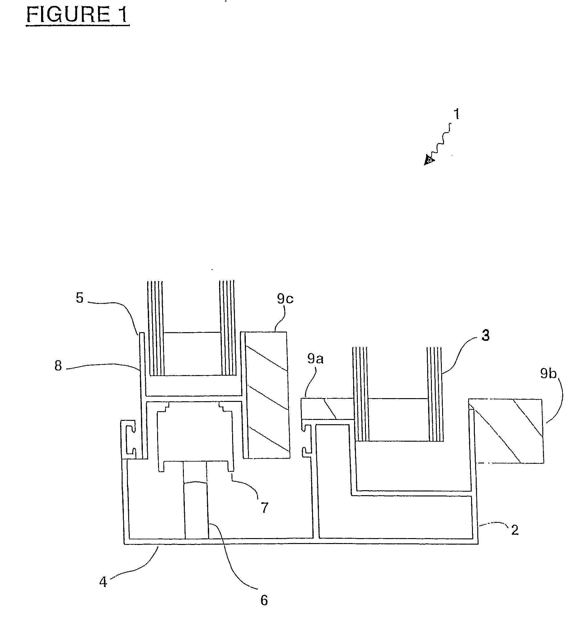
[0130]FIG. 1 shows a side cross section view of an existing prior art composite clad joinery system.

[0131] The bottom or sill sections of the joinery assembly (1) shown illustrate a bottom rolling sliding panel which is located on the exterior side of the joinery.

[0132] The joinery (1) provides a fixed panel form (2) which locates a fixed panel (3). Also provided is a sliding panel form (4) which locates a sliding panel (5). The sliding panel (5) runs along a single monorail track (6) in the sill of the sliding panel form (4) using a carriage (7) linked to the underside of the panel framing components (8).

[0133] The joinery assembly (1) also includes various sections of cladding material (9) installed to improve the thermal insulative properties of the resulting joinery. Cladding components (9a), (9b) are applied to the exposed surfaces of the fixed panel form. Conversely, an additional cladding component (9c) is needed to cover and insulate further exposed surfaces of the slidin...


PUM

PropertyMeasurementUnit
lengthaaaaaaaaaa
thermal performanceaaaaaaaaaa
temperatureaaaaaaaaaa

Abstract

A joinery assembly which includes a fixed panel form (32) is adapted to receive and locate a fixed panel (33), where at least a portion of the exposed surfaces of the fixed panel form are covered by a cladding material (39). The joinery system also includes a movable panel forms (34a, 34b), each adapted to receive a movable panel such as a sliding panel (35a) and / or a hinged panel (35b) respectively, where each of the movable panels has an interior surface and an exterior surface. At least a portion of the interior surface of a movable panel received by a movable panel form is covered by the cladding material applied to the exposed surfaces of the fixed panel form.

Description

TECHNICAL FIELD [0001] This invention relates to an improved joinery system. [0002] Preferably the present invention may be employed to provide a composite material joinery system with an improved thermal performance and aesthetic appeal to consumers. [0003] Reference throughout this specification will also be made to the joinery system provided employing aluminium in combination with either wood or polyvinyl chloride (μPVC) in its construction, but those skilled in the art should appreciate that potentially other materials may also be used if required. BACKGROUND ART [0004] Joinery is used to frame and mount glazing in the windows and entrance ways of buildings. [0005] Traditionally, wooden joinery has been employed for such purposes. Wooden joinery functions effectively to provide both an aesthetically attractive interior for a window or doorway and also performs well as a thermal insulator. [0006] Thermal insulation is important in joinery to ensure that the temperature at the ex...

Claims


Application Information

Patent Timeline
Patent Type & Authority Applications(United States)
IPC IPC(8): E06B3/32E06B3/26E06B3/263
CPCE06B1/342E06B3/4618E06B3/303
Inventor HANCOCK, MICHAEL JOHN
Owner HPJ HLDG
Why Eureka
Try Eureka