Vacuum heat insulator and heat insulating box using the insulator

An insulating material and vacuum heat technology, which can be applied to heat exchange equipment, pipeline protection through heat insulation, heat preservation, etc. It can solve the problems of increasing the weight and production cost of vacuum heat insulating materials, achieve good thermal insulation performance, and solve the problem of excessive compressors. Effects of Operational Efficiency Issues

Inactive Publication Date: 2001-09-12
MATSUSHITA REFRIGERATION
View PDF3 Cites 2 Cited by
  • Summary
  • Abstract
  • Description
  • Claims
  • Application Information

AI Technical Summary

Problems solved by technology

[0013] However, the conventional structure using a large amount of silica powder would unnecessarily increase the weight and production cost of the vacuum thermal insulation material

Method used


Image

  • Vacuum heat insulator and heat insulating box using the insulator
  • Vacuum heat insulator and heat insulating box using the insulator
  • Vacuum heat insulator and heat insulating box using the insulator

Examples


Embodiment approach 1

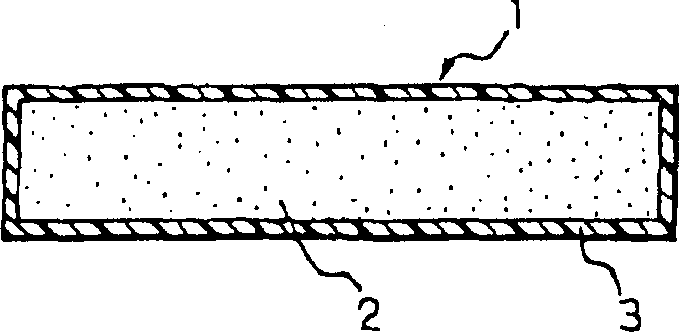
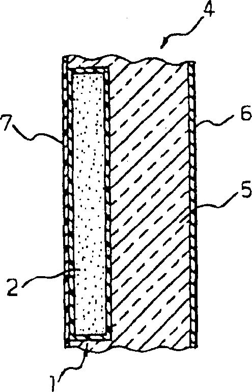
[0051] use figure 1 and 2 Embodiment 1 of the present invention will be described. figure 1 It is a cross-sectional view of the vacuum thermal insulation material according to Embodiment 1 of the present invention; figure 2 It is a sectional view of a heat insulating case using a heat insulating material according to Embodiment 1 of the present invention.

[0052] refer to figure 1 The vacuum heat insulating material 1 comprises a powder mixture obtained by stirring pulverized polyurethane foam powder having an average particle diameter of 150 μm and synthetic silica powder with a stirring mill at high speed (3600 rpm). The grinding powder of the polyurethane foam is obtained by grinding the polyurethane foam on a 150 μm abrasive cloth.

[0053]The prepared powder mixture is filled into a gas-permeable nonwoven fabric to form a core material 2 . The core 2 is placed in an outer part 3 consisting of a metal-plastic film laminate. The gas in the inner space surrounded by ...

Embodiment approach 2

[0068] Described below are the vacuum heat insulating material 1 and the heat insulating box 4 using the vacuum heat insulating material in Embodiment 2 of the present invention. The structure and figure 1 and 2 The embodiment 1 described in is the same and will not be specifically described here.

[0069] The vacuum heat in Embodiment 2 can be prepared by filling the mixture of ground polyurethane foam and synthetic silica powder into the outer layer member 3 made of a metal-plastic film laminate, and then sealing the outer layer member 3 under reduced pressure. Insulation Materials.

[0070] Polyurethane

Specific surface area (m 2 / g)

5

10

15

20

22

25

27

29

31

33

35

37

powder explosion

-

-

-

-

+

+

+

+

+

+

+

+

[0071] Polyurethane

Specific surface area (m ...

Embodiment approach 3

[0089] Described below are the vacuum thermal insulating material 1 and the thermal insulating case 4 using the vacuum thermal insulating material in Embodiment 3 of the present invention. The structure of the vacuum thermal insulation material 1 and thermal insulation box 4 of embodiment 3 figure 1 and 2 The embodiment 1 described in is the same and will not be specifically described here. In Embodiment 3, seven examples are discussed.


PUM

PropertyMeasurementUnit
specific surface areaaaaaaaaaaa
particle sizeaaaaaaaaaa

Abstract

A vacuum thermal insulating material of the present invention and a thermally insulating case using the vacuum thermal insulating material are used as thermal insulation in, for example, refrigerators and freezers. The vacuum thermal insulating material has a core material including two or more different powders and an adsorbent. The vacuum thermal insulating material of the present invention has excellent performance of thermal insulation and is light in weight and manufactured at a low cost. The thermally insulating case of the present invention enables the performance of thermal insulation to be practically maintained over a long time period.

Description

technical field [0001] The present invention relates to a vacuum heat insulating material used as heat insulation in, for example, refrigerators and freezers and a heat insulating box using the vacuum heat insulating material. technical background [0002] Chlorofluorocarbon 11 (referred to herein as CFC 11 ) has been used as a blowing agent for heat insulating materials used in, for example, refrigerators and freezers, and the destruction of the ozone layer caused by CFC 11 has been a concern for global environmental protection. [0003] Under such circumstances, there have been some studies focused on developing thermal insulating materials using novel blowing agents, which are blowing agents replacing CFCs or blowing agents other than CFCs replacing CFC11. A common example of a blowing agent that replaces CFC is hydrochlorofluorocarbon 141b (HCFC 141b). A typical example of a non-CFC blowing agent is cyclopentane. [0004] These novel blowing agents have a higher gas th...

Claims


Application Information

Patent Timeline
Patent Type & Authority Patents(China)
IPC IPC(8): F16L59/065
CPCF16L59/065
Inventor 谷本康明宫地法幸
Owner MATSUSHITA REFRIGERATION
Why Eureka
Try Eureka