
Heat Insulating Material

a heat insulation material and heat insulation technology, applied in the field of heat insulation materials, can solve the problems of low heat resistance and unknown thermal conductivity, and achieve the effects of excellent heat resistance, excellent heat insulation performance, and high strength

Active Publication Date: 2015-12-24
COORSTEK INC
View PDF3 Cites 2 Cited by
  • Summary
  • Abstract
  • Description
  • Claims
  • Application Information

AI Technical Summary

Benefits of technology

The heat insulating material described in this patent has better heat insulating properties than existing materials. It has excellent heat resistance and compressive strength at high temperatures. Additionally, its thermal conductivity increase is suppressed, which means it performs better as a heat insulating material in high temperature regions. Overall, this material is much more suitable than existing materials for use in high temperature regions.

Problems solved by technology

However, such a heat insulating material mainly contains silica aerogel, has low heat resistance, and has unknown thermal conductivity at a high temperature of 400° C. or higher.

Method used


Image

  • Heat Insulating Material
  • Heat Insulating Material

Examples


example 1

[0079]Mixing was performed at a ratio of 11 mol of hydraulic alumina powder (BK-112, manufactured by Sumitomo Chemical Co., Ltd.) to 9 mol of magnesium oxide powder (MGO11PB, manufactured by Kojundo Chemical Laboratory Co., Ltd.). Pure water equivalent in weight to a total weight of hydraulic alumina and magnesium oxide was added thereto. The resultant mixture was dispersed uniformly to prepare a slurry.

[0080]Then, a granular acrylic resin having a diameter of 10 μm was added to the slurry at a ratio of 50 vol % with respect to the slurry as a pore forming material for mixing. The resultant mixture was molded to obtain a molded body of 60 mm×70 mm×20 mm.

[0081]This molded body was fired at 1800° C. for three hours in the atmosphere to manufacture a porous sintered body.

[0082]A crystal phase of the porous sintered body obtained above was identified by X-ray diffraction (apparatus for X-ray diffraction: manufactured by Rigaku Corporation, RINT2500, X-ray source: CuKα, voltage: 40 kV, c...

example 3

[0100]Mixing was performed at a ratio of 11 mol of hydraulic alumina powder (BK-112, manufactured by Sumitomo Chemical Co., Ltd.) to 9 mol of magnesium oxide powder (MGO11PB, manufactured by Kojundo Chemical Laboratory Co., Ltd.). Pure water equivalent in weight to a total weight of hydraulic alumina and magnesium oxide was added thereto. The resultant mixture was dispersed uniformly to prepare a slurry. Then, a granular acrylic resin having a diameter of 10 μm was added to the slurry at a ratio of 50 vol % with respect to the slurry as a pore forming material for mixing. The resultant mixture was molded to obtain a molded body of 60 mm×70 mm×20 mm. This molded body was fired at 1600° C. for three hours in the atmosphere to manufacture a porous sintered body.

[0101]A crystal phase of the porous sintered body obtained above was identified by powder X-ray diffractometry (apparatus for X-ray diffraction: manufactured by Rigaku Corporation, RINT2500, X-ray source: CuKα, voltage: 40 kV, c...


PUM

PropertyMeasurementUnit
porosityaaaaaaaaaa
porosityaaaaaaaaaa
pore diameteraaaaaaaaaa

Abstract

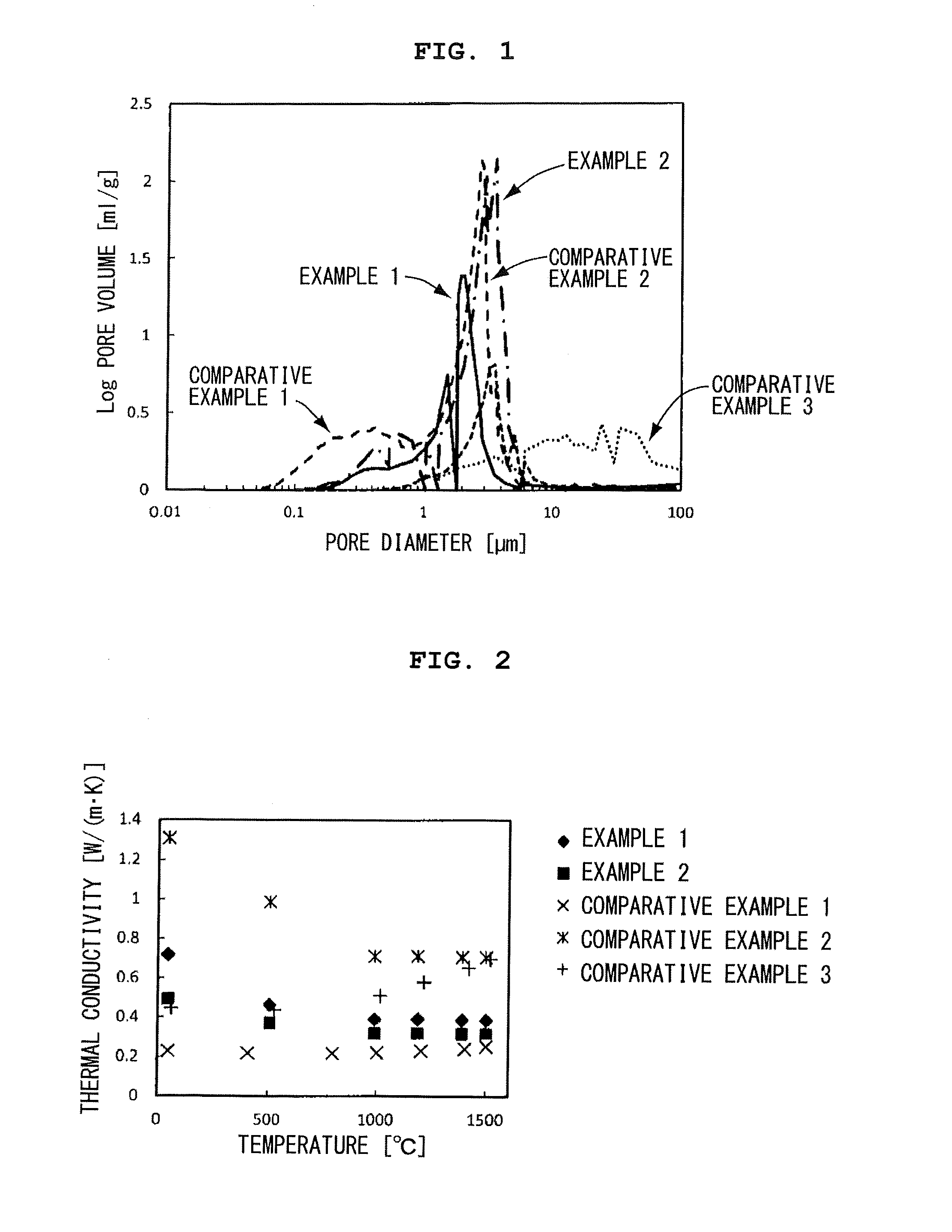
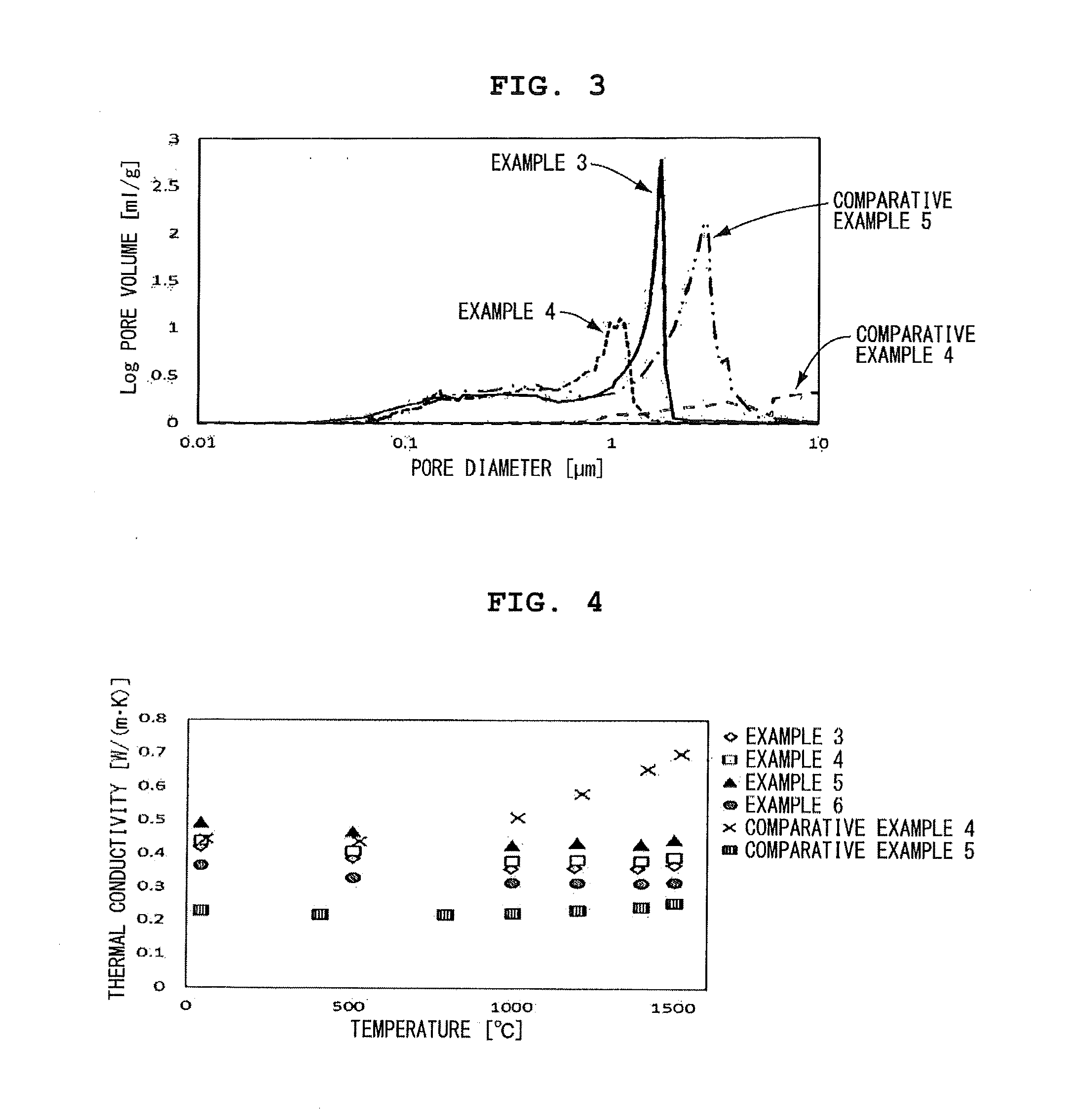
A heat insulating material includes a porous sintered body formed of MgAl2O4 and having a porosity of 60% or more and less than 73%. In the heat insulating material, pores having a pore diameter of 0.8 μm or more and less than 10 μm occupy 30 vol % or more and less than 90 vol % of a total pore volume, pores having a pore diameter of 0.01 μm or more and less than 0.8 μm occupy 10 vol % or more and less than 60 vol % of the total pore volume, the thermal conductivity at 20° C. or higher and 1500° C. or lower is 0.45 W / (m·K) or less, and the compressive strength is 2 MPa or more.

Description

BACKGROUND OF THE INVENTION[0001]1. Technical Field[0002]The present invention relates to a heat insulating material including a porous sintered body of MgAl2O4 and having excellent heat insulating performance at a high temperature of 1000° C. or higher.[0003]2. Description of the Related Art[0004]The heat insulating material is required to have low thermal conductivity. A fiber-based heat insulating material such as glass fiber, ceramics having a low bulk density, such as a ceramic porous body, or the like is generally used. A heat transfer factor having an influence on the thermal conductivity can be considered by dividing the heat transfer factor into solid heat transfer, gas heat transfer, and radiation heat transfer.[0005]For example, JP 2009-299893 A describes a fiber-based heat insulating material including a fiber material filled with aerogel. In the fiber-based heat insulating material, a heat insulating layer including an infrared reflection agent is coated with a porous c...

Claims


Application Information

Patent Timeline
Patent Type & Authority Applications(United States)
IPC IPC(8): C01F7/47F16L59/02
CPCC01F7/47F16L59/028C01P2006/14C01P2006/16C01P2006/32C04B35/443C04B35/634C04B38/0615C04B2111/27C04B2235/602F16L59/00
Inventor AKAMINE, SHUKOFUJITA, MITSUHIRO
Owner COORSTEK INC
Learn More