Combined pressure and temperature sensor

a temperature sensor and pressure sensor technology, applied in the direction of instruments, measurement device, measurement apparatus components, etc., can solve the problems of high cost, high cost, and high cost of two sensors, and achieve the effect of increasing the accuracy of temperature measurement, simple construction and cost-effectiveness

Inactive Publication Date: 2007-08-16
ROBERT BOSCH GMBH
View PDF7 Cites 12 Cited by
  • Summary
  • Abstract
  • Description
  • Claims
  • Application Information

AI Technical Summary

Benefits of technology

[0012] Because of the design approach provided according to the present invention, the signal of the temperature sensor, which passes through the sensor element of the combined pressure and temperature sensor, can be conveyed right up to the plug contact. Alternatively, the signal of the temperature sensor obtained is able to be evaluated and adjusted in an evaluation circuit. According to this alternative, a digital evaluation circuit is used for this purpose, having a digital interface. This offers the possibility of omitting one plug pin and increasing the accuracy of the temperature measurement.
[0013] The design approach provided according to the present invention stands out over the design approaches of the related art in that an extremely simple construction comes about, as well as making cost-effective manufacturing possible, since only a few components are used. In particular, it is very easy to manufacture the combined pressure and temperature sensor provided according to the present invention in mass production. The provided temperature sensor, that is used in the combined pressure and temperature sensor according to the present invention, operates independently of the pressure measurement, and is distinguished by a rapid response time.

Problems solved by technology

The use of two sensors represents a considerable expenditure, since at least two plug connectors and several strands of cable have to be held in reserve, as well as sealing locations that have to be sealed at the interface locations and connecting locations of the individual components among one another.
However, this design approach suffers from the disadvantage that the front diaphragm sensor is very sensitive in the vicinity of the diaphragm, and a protective screen should be preconnected.
In the case of this design approach, it is used in racing car applications whose service life is extremely short.
However, the O-ring becomes brittle during a longer operating period, so that leakage sets in.
Based on the circumstance that the diaphragm is located relatively far from the measured medium, the temperature signal received is too inaccurate.
However, in order to measure as far as possible in the measured medium, a complex construction technology and connecting technology are used.
If the sensor extends into the measuring channel, it narrows down the channel, because of its cross section, to such an extent that considerable pressure reduction can occur, which impairs the measurement of the pressure signal.
The design approaches sketched above, known from the related art, do not represent satisfactory solutions for the reasons mentioned.

Method used


Image

  • Combined pressure and temperature sensor
  • Combined pressure and temperature sensor
  • Combined pressure and temperature sensor

Examples


Embodiment Construction

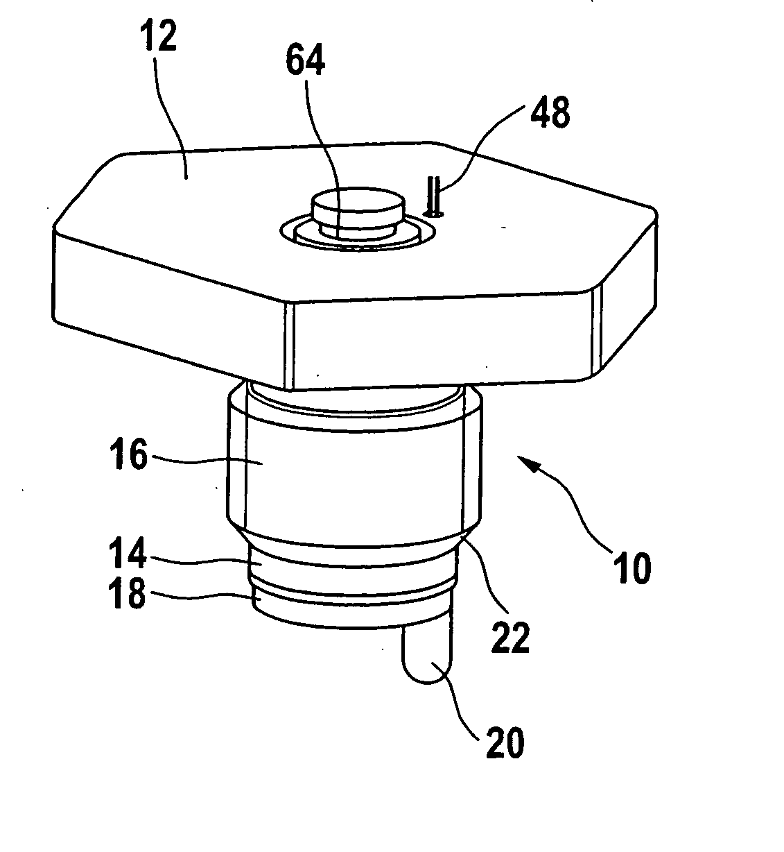
[0021] In the representation according to FIG. 1, a perspective view will be seen of the combined pressure and temperature sensor proposed according to the present invention.

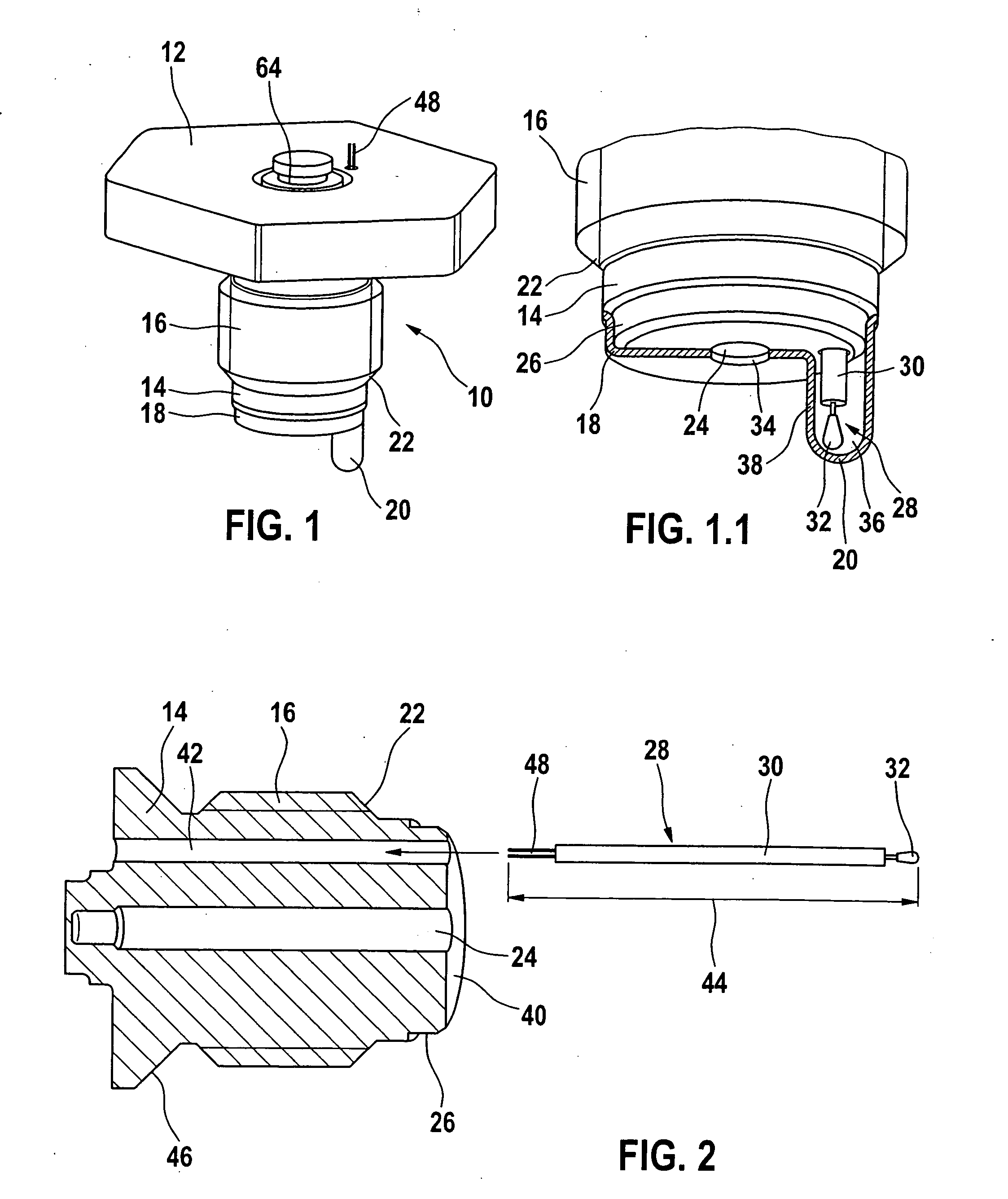
[0022] A combined pressure and temperature sensor 10 includes a tool connection 12, which is developed in the illustration according to FIG. 1 as a hexagonal connection. A sensor element 14 extends below tool connection 12, and it has a threaded section. Threaded section 16 runs out in a screw thread runout 22. At the lower end of sensor element 14 a cover 18 is accommodated, designed as a front plate, which has a finger-shaped projection 20 for accommodating a temperature sensor. The pressure measuring part of combined pressure and temperature sensor 10 is shown by a through-hole 24 that passes through sensor element 14 and is not shown in FIG. 1 (cf. FIG. 1.1), which acts upon a diaphragm 64. Diaphragm 64 is preferably developed as a steel diaphragm to which a metallic thin-layer bridge circuit is applied, wh...


PUM

PropertyMeasurementUnit
pressureaaaaaaaaaa
lengthaaaaaaaaaa
heat-conductingaaaaaaaaaa

Abstract

A combined pressure and temperature sensor for recording the pressure and the temperature of a medium. A sensor element of the combined pressure and temperature sensor includes a through-hole to a diaphragm and a bore for accommodating a temperature sensor. The diaphragm cooperates with a pressure sensor. At an end face of the sensor element, on the side of the medium, a cover is fastened, in which a hollow space is developed to accommodate the temperature sensor.

Description

BACKGROUND INFORMATION [0001] For future air conditioning systems installed in motor vehicles, it is to be expected that the usual R134a air conditioners will be replaced by CO2 air conditioners, since, according to EU legislation, the cooling agent R134a, used up until now, will be totally prohibited as of the year 2016. [0002] By contrast to the conventional air conditioner that is operated using cooling agent R134a, in the CO2 air conditioner, both a pressure signal and a temperature signal from the compressor of the air conditioner will be required for the regulation of the air conditioner. The use of two sensors represents a considerable expenditure, since at least two plug connectors and several strands of cable have to be held in reserve, as well as sealing locations that have to be sealed at the interface locations and connecting locations of the individual components among one another. An attempt is made, therefore, to obtain both the pressure signal and the temperature sig...

Claims


Application Information

Patent Timeline
Patent Type & Authority Applications(United States)
IPC IPC(8): G01L19/04
CPCG01D11/245G01L19/0092G01K13/02
Inventor ENGELHARDT, JOERGSTOLL, OLIVERROESSER, CHRISTIANLEDERMANN, MARKUSWARTH, STEFAN
Owner ROBERT BOSCH GMBH
Why Eureka
Try Eureka