Systems and methods for delivering flow restrictive element to airway in lungs

a technology of flow restriction and airway, applied in the field of medicine, can solve the problems of extended procedure time and frustration for operators, inability to retrieve inaccurately placed stents within acceptable procedural time limits, and inability to perform catheter-based therapeutic procedures

Inactive Publication Date: 2007-08-16
PULMONX
View PDF4 Cites 176 Cited by
  • Summary
  • Abstract
  • Description
  • Claims
  • Application Information

AI Technical Summary

Benefits of technology

[0012] In a second aspect of the present invention, a system comprises a self-expanding flow restrictive element adapted for release to occlude an airway in a lung. Such element may either be a fully flow restrictive element, such as a self-expanding scaffold covered by an air impermeable barrier, or may alternatively be a one-way valve structure which when implanted permits air to be expelled from the isolated lung region but which prevents air from re-entering said lung region. The system further comprises a delivery sheath having at least one lumen adapted to recede and constrain

Problems solved by technology

A significant drawback of the systems and techniques currently available is the ability to maintain a hold of the stent prior to fully releasing it which can result in an inaccurately placed stent that can not be removed or re-positioned or requires a device exchange to do so.
A device exchange can lead to extended procedure time as well as frustration to the

Method used


Image

  • Systems and methods for delivering flow restrictive element to airway in lungs
  • Systems and methods for delivering flow restrictive element to airway in lungs
  • Systems and methods for delivering flow restrictive element to airway in lungs

Examples


first embodiment

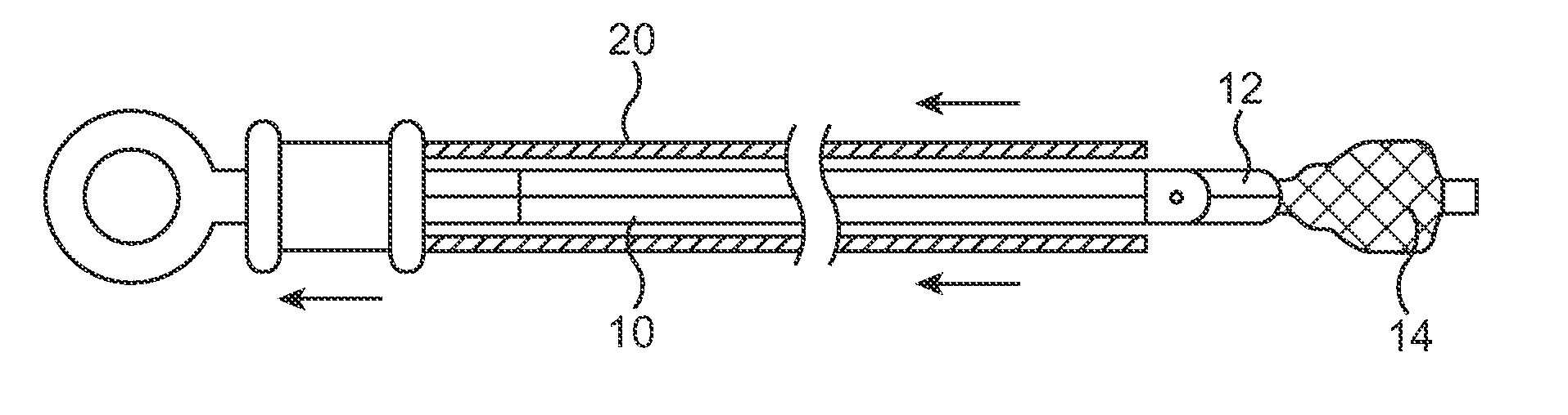
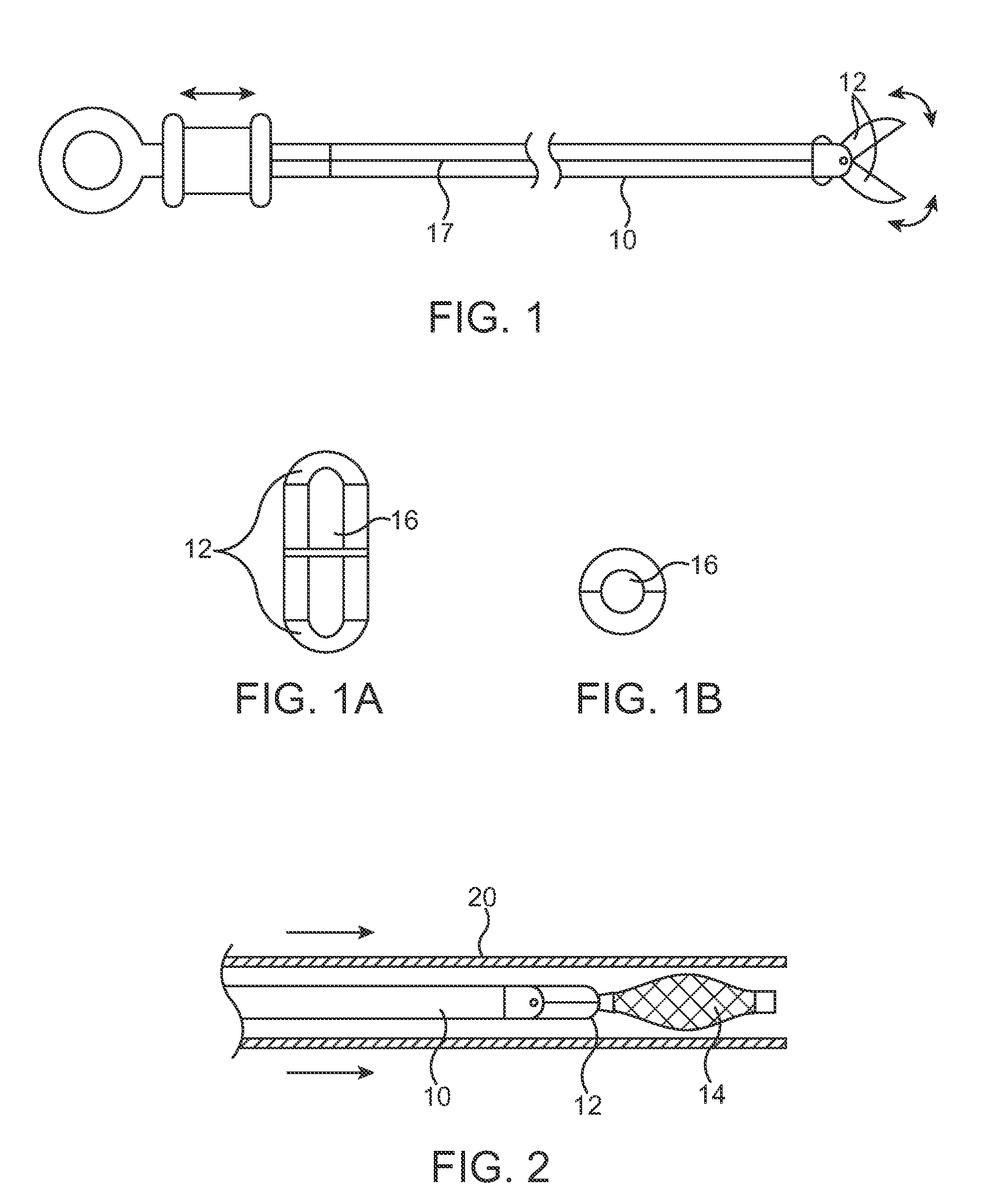
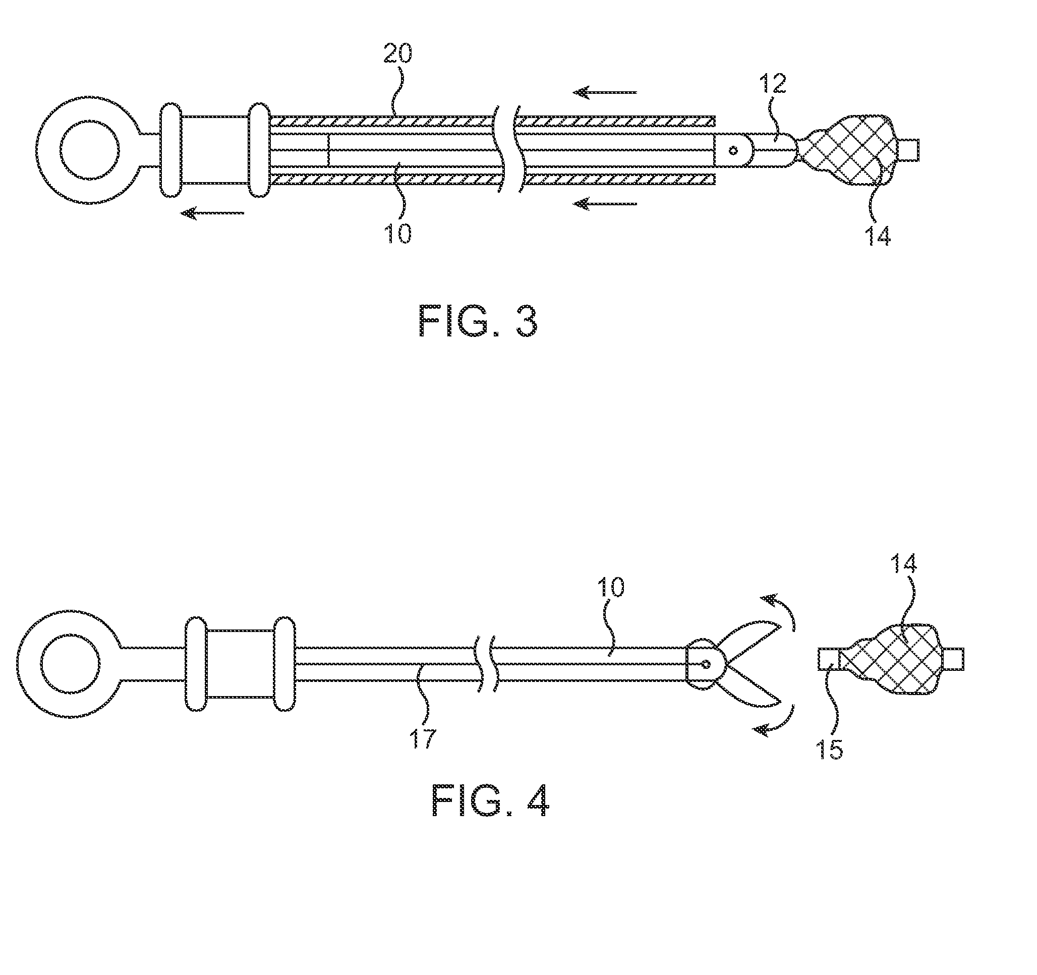
[0061]FIG. 4A describes an alternative configuration of the release mechanism. The modified graspers or biopsy forceps 10 used in the first embodiment can also have an additional mechanism in the proximal end that biases the jaws to be in the open position. A pull wire 17 of the graspers is designed to be “pull to close”. A piston 22 is fixed to wire 17 and combined with a compression spring 24 or a “jaw opening spring” maintains a “push” force on the wire. This type of loading forces the jaws to open when unconstrained. The loading can be low enough that the outer sheath 20 constrains the jaws 12 to the closed position but high enough to allow the jaws 12 to open freely when unsheathed. This greatly simplifies the hand manipulations required of the operator because the steps to unsheathe the stent will also unsheathe the jaws. It allows for a more intuitive and automated release of the stent. FIG. 4A also shows the actuation barrel 26 of the proximal handle housing a final release ...

third embodiment

[0065]FIG. 9 describes this invention. A loop snare 50 is formed from a wire or string and is configured to snare the stent 14. A proximal end 52 of the wire or string is attached to an actuator handle 54 that enables remote tightening or loosening of the snare on the stent. FIG. 10 illustrates the loop 50 of the distal end of the wire or string in detail. The loop is configured in such a way that allows for tightening of the snare when placed in tension and loosening of the snare when tension is released and / or compression is placed on it. One means of accomplishing this is to place an eyelet 51 at the end of the wire or string and then to run the other end of the wire or string through the eyelet. Pulling on the wire or string tightens the snare and releasing or pushing the wire or string loosens the snare. The loop 50 snaring a proximal end of the stent 14 is shown in FIGS. 11A and 11B. The loop tightens down on the proximal end of the stent snaring it. This action maintains a ho...

fourth embodiment

[0070]FIGS. 17A-17C describes three different keying configurations that can be used for this invention. One configuration has a center round hole with rounded slots at the 90 degree position and the 270 degree position (FIG. 17A). The next configuration has a more elliptical or oval shape (FIG. 17B). The last configuration shown has a center round hole with square slots at the 90 degree position and the 270 degree position (FIG. 17C). Each of these configurations operates similarly in that a hole of these shapes will accept a smaller rod of these shapes. A 90 degree rotation of the rod with respect to the hole will engage the two components and provide an interference. This interference allows the two components to stay attached. Just as a 90 degree rotation allows the two components to engage, another 90 degree rotation allows the two components to disengage. Disengagement can occur when the longer features located at 90 degrees and 270 degrees are aligned with respect to the two ...


PUM


Abstract

A method and system for catheter-based delivery of implants in the body. Implants can include stents, plugs, coils, baskets, filters, valves, grafts, prosthesis', drugs, drug reservoirs, biologics, or pumps. The catheter system comprises a uniquely configured grasper mechanism that allows holding the implant during the unsheathing delivery step prior to full release. With this delivery system, the implant can be unsheathed, positioned, and the position can be evaluated prior to releasing the implant from the catheter. Upon evaluation of the position of the implant, if it is found to be inaccurately placed, then removal of the implant can be done easily and without a device exchange. If the implant is found to be positioned correctly, the grasper mechanism can be actuated to release the implant from the catheter.

Description

CROSS-REFERENCES TO RELATED APPLICATIONS [0001] This application claims the benefit of provisional application No. 60 / 759,713 (Attorney Docket No.: 017534-003400US), filed on Jan. 17, 2006, the full disclosure of which is incorporated herein by reference.BACKGROUND OF THE INVENTION [0002] The subject invention relates to the field of medicine and to the field of performing catheter-based therapeutic procedures within the body. In particular the invention relates to delivering implants or biologics into the airways of the lungs for interventional purposes. [0003] Tubular structures exist in many organ systems within the body, such as in the circulatory system, the cardiovascular system, the reproductive system, gastrointestinal system, otolaryngology system, and the respiratory system. Specific structures may include airways, fallopian tubes, bile ducts, blood vessels, or the esophagus. Further, artificially created lumens can exist. Tubular systems can be accessed from outside the b...

Claims


Application Information

Patent Timeline
IPC IPC(8): A61B17/00A61M16/00
CPCA61B17/12022A61B17/12104A61B17/12172A61B17/221A61B2017/22035A61B2017/12095A61F2/95A61F2002/011A61F2002/9528A61B2017/12054A61B2017/2215A61F2/966A61F2002/9534A61F2/011A61F2/9517
Inventor DOMINGO, NICANORLEE, JEFFREYWONDKA, ANTHONYSURJAN, GEORGEFREITAG, LUTZ
Owner PULMONX
Why Eureka
Try Eureka