Front mounted pump

a front mounted, pump technology, applied in the direction of positive displacement liquid engine, agricultural machinery, agricultural tools and machines, etc., can solve the problems of affecting the operation of the pump, too large and too expensive for other purposes, and the damage of the case, so as to improve the efficiency of the operation and facilitate the operation

Inactive Publication Date: 2007-08-16
LOWELL SCOTT ENTERPRISES
View PDF12 Cites 1 Cited by
  • Summary
  • Abstract
  • Description
  • Claims
  • Application Information

AI Technical Summary

Benefits of technology

[0016] The suction hose is preferably substantially shorter than the discharge hose, and is short and rigid enough to remain conveniently attached to the pump's inlet opening during transport. For example, a preferred hose has a length of from about 3 to 8 feet, a diameter of about 3 to 4 inches, and a bend radius of about at least 8 inches, e.g., from about 8 to 15 inches. A preferred hose is a semi-rigid hose of reinforced PVC. Tractors such as those usable with the present invention typically have front hitch hydraulic lifts that can raise the frame and pump high enough off the ground surface to prevent the end of the rigid suction hose from striking the ground during transport. Thus, the suction hose need not be detached and reattached between pumping applications. Moreover, since the frame and pump are hitched to the front of a compact tractor, the tractor can be driven as close as needed to the water to be evacuated, making it very convenient for the operator. Better still, because the pump is mountable to the front of a tractor it eliminates the need for a long suction hose, thus making any given pumping application more energy efficient. It will be understood, however, that for some applications the shorter front hose can be replaced with a longer, more flexible hose.

Problems solved by technology

While these large evacuation systems are suitable for large agricultural applications, they are too large and too expensive for other purposes such as evacuating water from golf course sand traps.
For one, driving large agricultural tractors into or near the edges of golf course sand traps would be very damaging to the sand traps.
To make matters worse, these type pumps are hitched to the rear of the tractor, making it necessary to back the large rear wheels of the tractor to near the edge of the sand trap causing worst case damage.
However, this solution results in inefficiencies inherent in using a longer intake hose, such as priming concerns, etc.

Method used


Image

  • Front mounted pump
  • Front mounted pump
  • Front mounted pump

Examples


Embodiment Construction

[0030] In the following description, terms such as horizontal, upright, vertical, above, below, beneath and the like are solely used for the purpose of clarity in illustrating the invention, and should not be taken as words of limitation. Also, like reference numerals represent like parts throughout the drawings. In addition, the drawings are for the purpose of illustrating the invention and are not intended to be to scale.

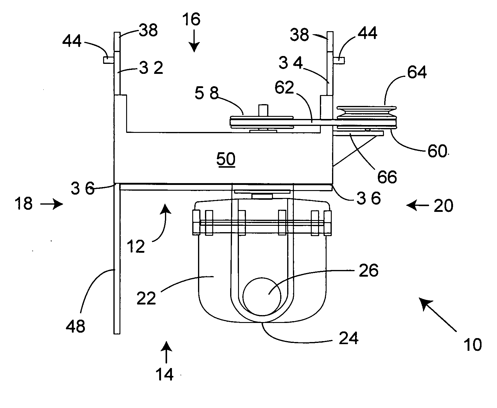
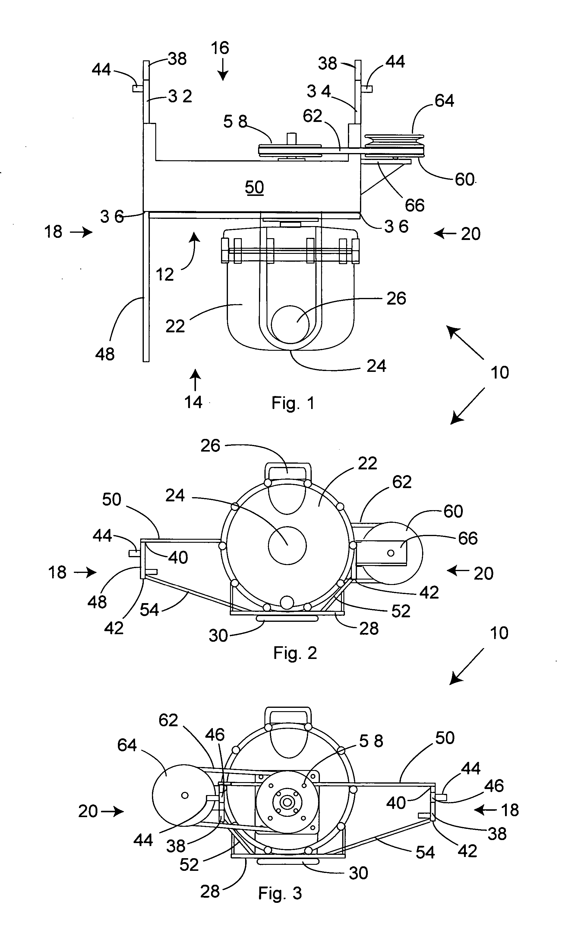
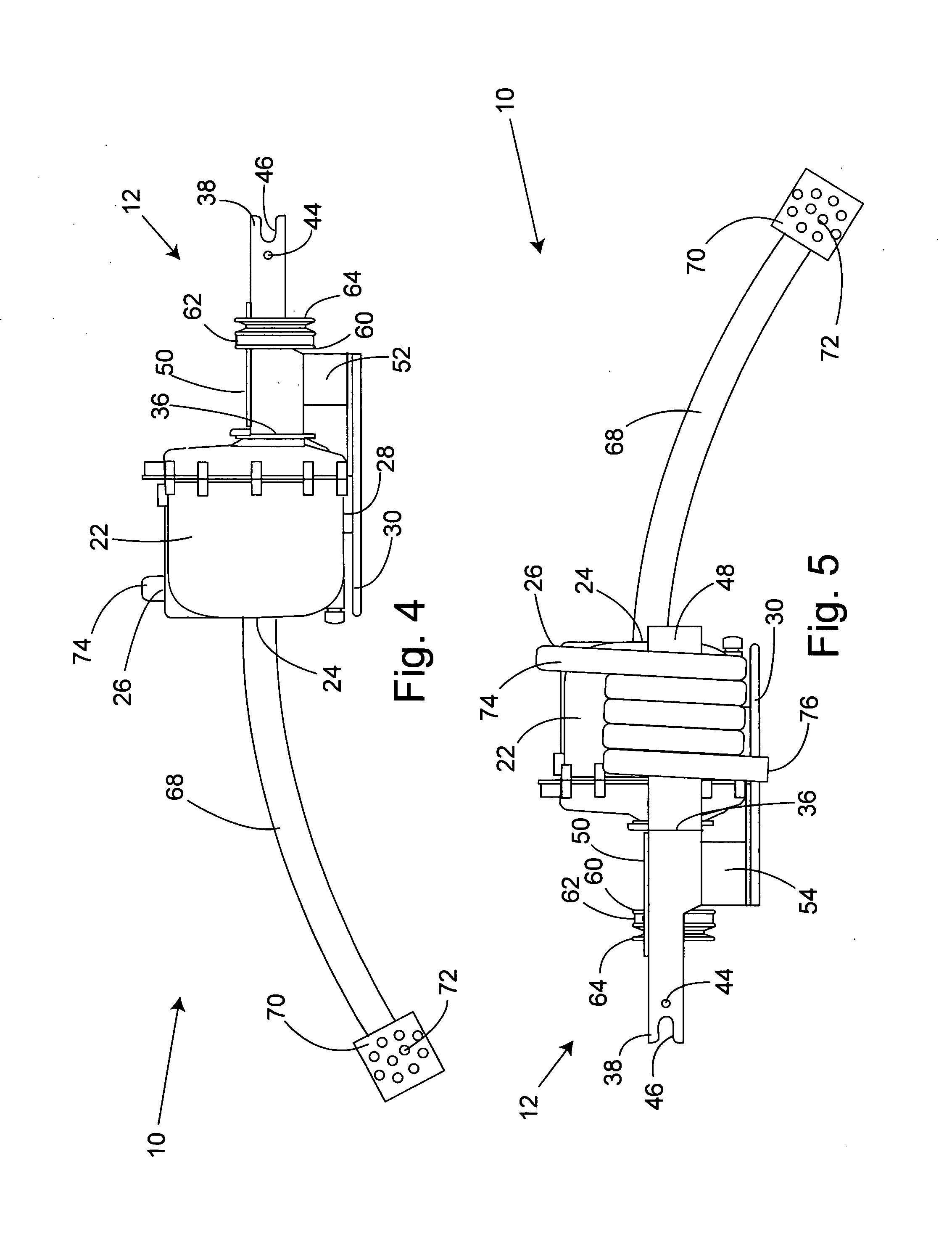
[0031]FIG. 1 depicts a top view of the front mountable pump apparatus of the present invention, generally 10. Pump apparatus 10 comprises a frame 12 having a front 14, rear 16, left 18 and right 20 side. A self-priming centrifugal pump 22 is attached to frame 12. Pump 22 has an intake opening 24 centered on the front of the pump and a discharge opening 26 at the top of the pump.

[0032] As best seen in FIGS. 2 and 3, frame 12 comprises a pump support beam 28 that extends between apparatus left 18 and right 20 sides. Pump 22 is secured to the support beam such that...


PUM


Abstract

An apparatus for use in combination with a tractor having a hydraulically adjustable front implement hitch and a front power takeoff is described for use in evacuating a body of water. The apparatus includes a mounting frame attachable to said front implement hitch; a pump having a water inlet, a water outlet and a rotatable drive shaft with a drive pulley carried on said mounting frame; drive means connecting said pump drive pulley to the front power takeoff; a suction hose having a proximal end attached to the water inlet of said pump and a distal end; and a discharge hose attached to the water outlet of said pump.

Description

[0001] This application claims the benefit of the filing date of U.S. Provisional Application Ser. No. 60 / 764,477, filed Feb. 2, 2006.BACKGROUND OF THE INVENTION [0002] (1) Field of the Invention [0003] The present invention relates to an apparatus for evacuating a body of water. In particular, the invention relates to a water evacuation system that can be mounted on the front of a tractor to drain water from bodies of standing water, such as flooded sand traps and other bodies of water on a golf course. [0004] (2) Description of the Prior Art [0005] Evacuation pumps are often used in agriculture to direct irrigation water from one location to another. Typically, a large capacity evacuation pump is powered by the rear power-take-off of a large size tractor. These large pumps are usually attached to the three-point hitch of the tractor, although some can be so large that they are towed in a tractor-trailer type configuration. [0006] While these large evacuation systems are suitable f...

Claims


Application Information

Patent Timeline
Patent Type & Authority Applications(United States)
IPC IPC(8): A01B23/04A01B15/14A01B35/20A01B39/24
CPCF04B17/05A01B59/064
Inventor MCFARLAND, DOUGLAS L.PAPPALARDO, CHRISTOPHER S.
Owner LOWELL SCOTT ENTERPRISES
Why Eureka
Try Eureka