
Lamb wave type frequency device and method thereof

a frequency device and a technology of a beam wave, applied in the direction of device material selection, generator/motor, impedence network, etc., can solve the problems of reducing yield, difficult to handle the substrate, hardly handling the device, etc., to achieve stable resonance property, enhance structural strength, and improve yield

Inactive Publication Date: 2007-08-16
SEIKO EPSON CORP
View PDF8 Cites 76 Cited by
  • Summary
  • Abstract
  • Description
  • Claims
  • Application Information

AI Technical Summary

Benefits of technology

The present invention provides a Lamb wave type high frequency device that has stable resonance property and is easily handled. The device includes a piezoelectric substrate and an IDT electrode formed on a first main surface of the piezoelectric substrate, a reinforcing substrate connected to a second main surface of the piezoelectric substrate, and a space portion formed in the piezoelectric substrate or the reinforcing substrate, an area of the space portion being larger than a region in which a Lamb wave is propagated. The space portion has a connecting surface formed in a periphery of the space portion. The device also includes a package that protects the piezoelectric substrate and the reinforcing substrate from outer environments. The package is air-tightly sealed, maintaining inside the package in vacuum and restraining energy loss at the IDT electrode. The space portion can be maintained in vacuum by vacuuming the package at only one time, even if the space portion is a groove-like recess with an opening at the side surface. The device also includes a method for manufacturing the device with the first aspect.

Problems solved by technology

In the above disclosures (patent documents and non patent documents), however, the thickness of the piezoelectric substrate is from several μm to several tens μm, thereby handling the substrate is difficult since it is easily broken.
Hence, such device is hardly handled and easily broken compared to the surface acoustic device, further, its yield is lowered.
Further, exciting characteristics are remarkably deteriorated when the IDT electrode is hurt.

Method used


Image

  • Lamb wave type frequency device and method thereof
  • Lamb wave type frequency device and method thereof
  • Lamb wave type frequency device and method thereof

Examples


first embodiment

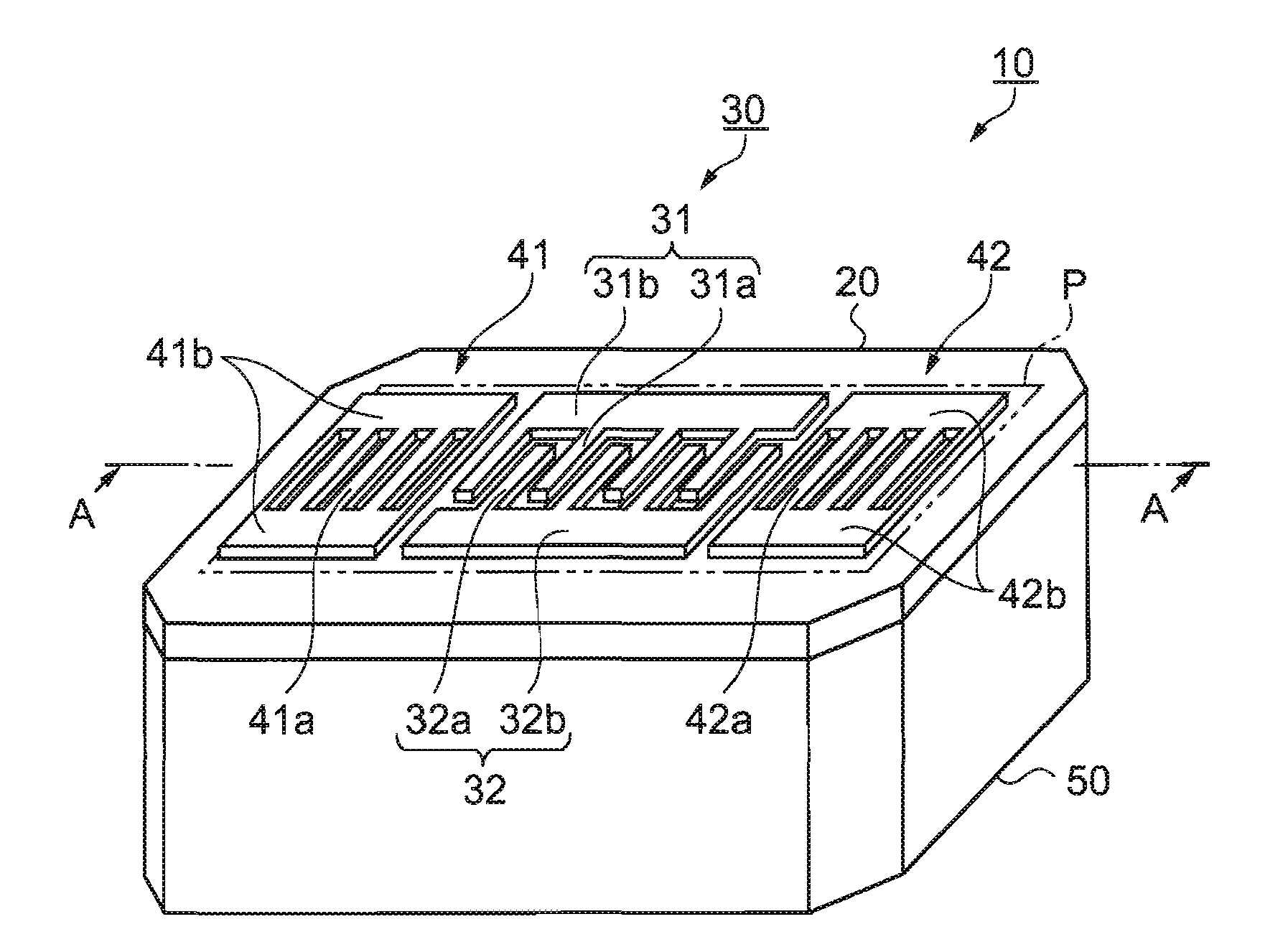
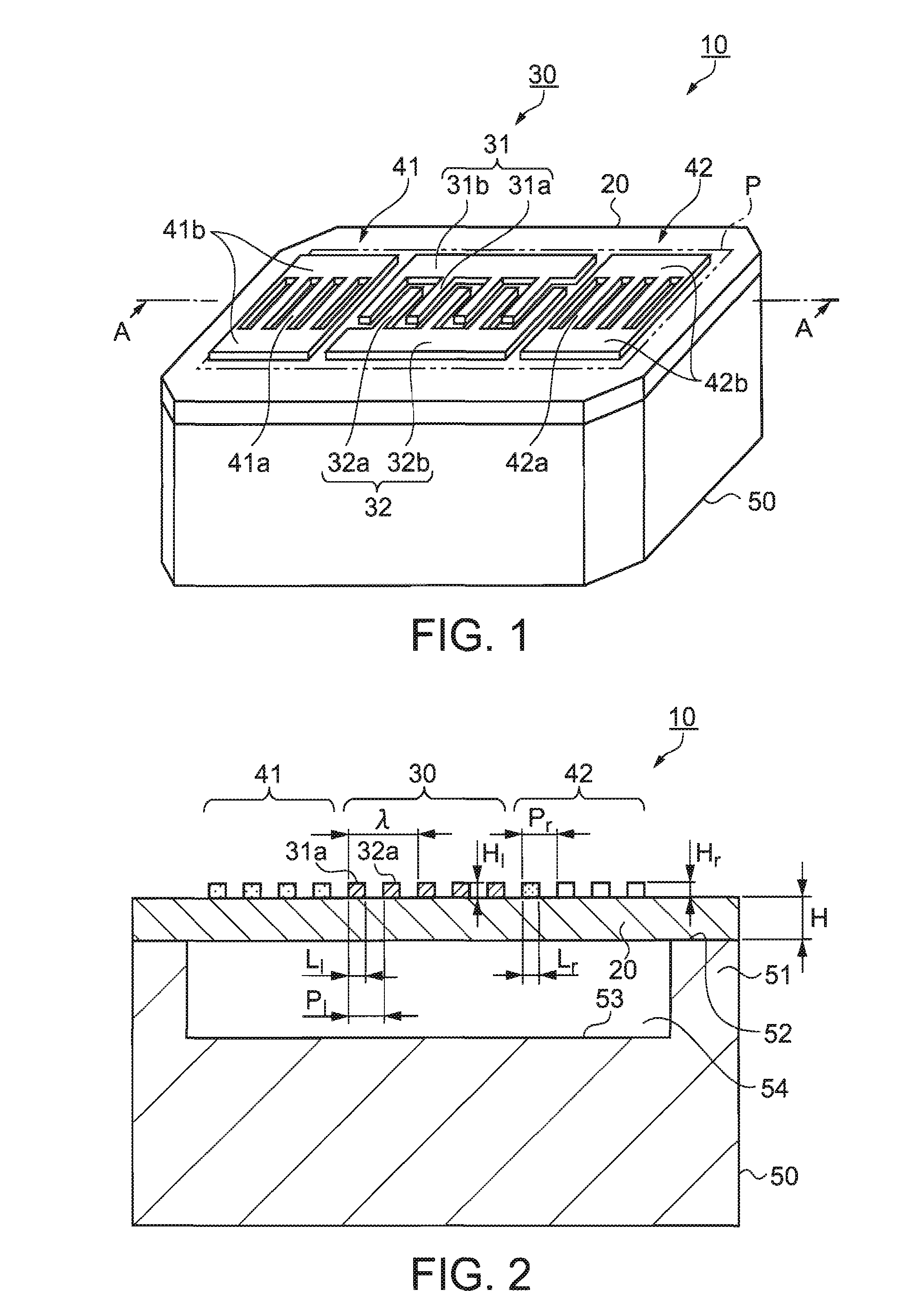
[0061]FIGS. 1 and 2 show a Lamb wave type high frequency device according to the first embodiment of the invention. FIG. 1 is a perspective view thereof and FIG. 2 is a sectional view schematically showing the A-A cut surface in FIG. 1. In FIG. 1, a Lamb wave type high frequency device 10 comprises a piezoelectric substrate 20 and a reinforcing substrate 50 that are connected each other.

[0062]The piezoelectric substrate 20 is a thin substrate made of quartz and having a uniform thickness. The substrate 20 comprises an IDT electrode 30, which is made of aluminum and has a comb-teeth shaped, on one main surface of it and a pair of reflectors 41 and 42 in the both sides of propagating direction of a Lamb wave from the IDT electrode 30. The IDT electrode 30 comprises an IN / OUT electrode 31 and a GND electrode 32. The IN / OUT electrode 31 is provided with a plurality of electrode fingers 31a and a bus bar 31b connecting the fingers 31a each other. The GND electrode 32 is provided with a p...

second embodiment

[0077]The second embodiment of the invention is explained with reference to a figure. In the second embodiment, the recess is provided in the piezoelectric substrate, though it is provided in the reinforcing substrate in the first embodiment shown in FIG. 2. The major difference from the first embodiment is explained.

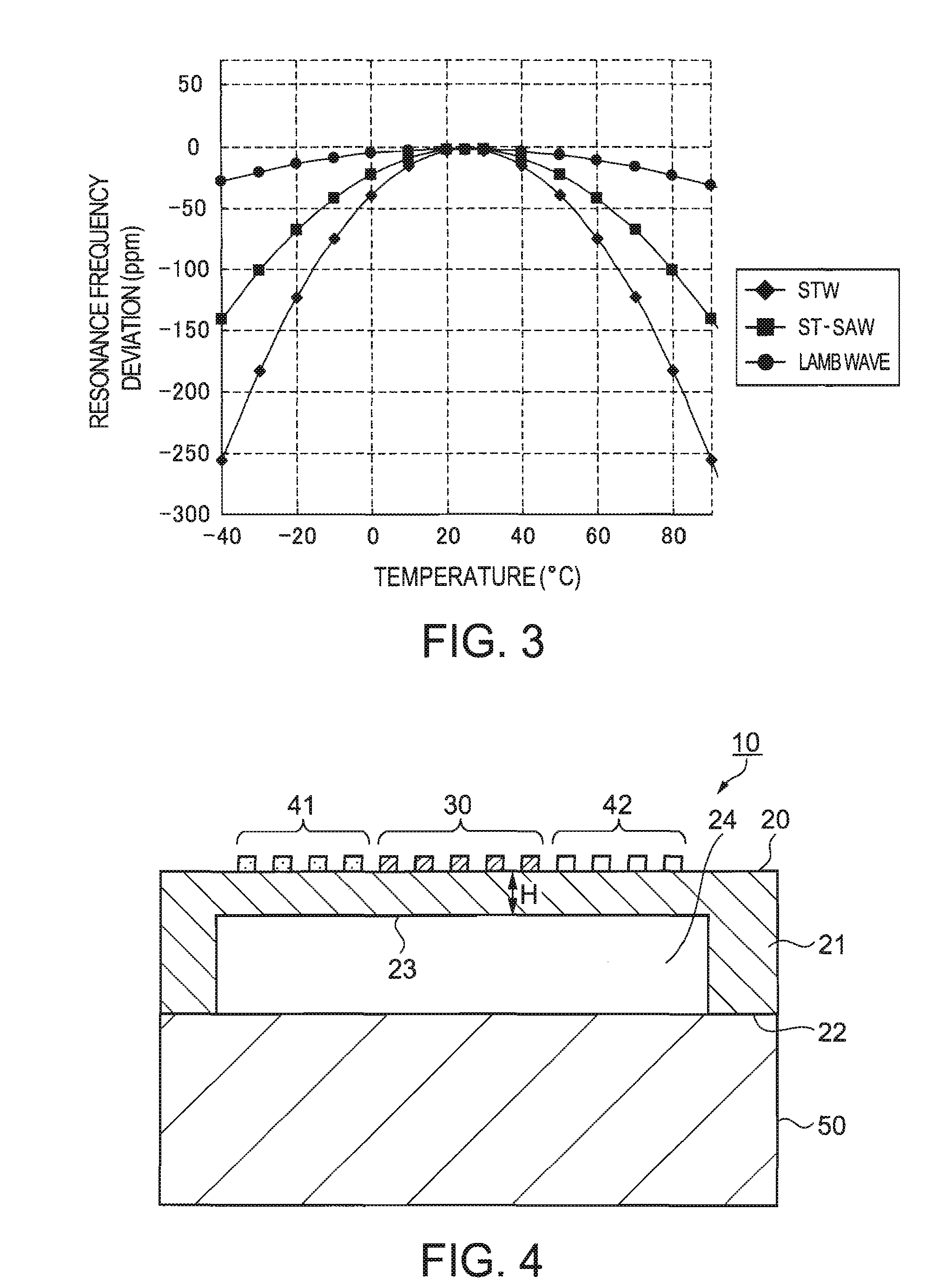
[0078]FIG. 4 is a sectional view schematically showing the Lamb wave type high frequency device 10 of the second embodiment. In FIG. 4, the IDT electrode 30 and the reflectors 41 and 42 are formed on the one surface (the front surface) of the piezoelectric substrate 20 and a boxlike recess 23 is provided to the other surface (the back surface) of it.

[0079]The thickness H at the bottom of the recess 23 is set to the following relationship regarding the wavelength λ of the Lamb wave: 021 is formed at the circumferential area of the recess 23 and a connecting surface 22 of the upper surface (the lower surface in the figure) of the edge portion 21 is bonded to the reinforci...

third embodiment

[0081]The third embodiment of the invention is explained with reference to a figure. In the third embodiment, the groove-like recess is provided in the reinforcing substrate, though the boxlike recess is provided in the reinforcing substrate in the first embodiment shown in FIG. 2. The major difference from the first embodiment is explained.

[0082]FIG. 5 is a sectional view schematically showing a Lamb wave type high frequency device 110 of the third embodiment.

[0083]In a reinforcing substrate 150, a groove-like recess 153 (an almost square C shape from the front view) is formed. The recess 153 is formed as crossing the reinforcing substrate 150, making the side surface of the width direction opened and a rim portion 151 is formed at both ends of the reinforcing substrate 150 in the longitudinal direction. Then, the piezoelectric substrate 20 is bonded to the reinforcing substrate 150 at a connecting surface 152 of the upper surface of the rim portion 151 by connecting means such as ...


PUM

PropertyMeasurementUnit
thicknessaaaaaaaaaa
areaaaaaaaaaaa
piezoelectricaaaaaaaaaa

Abstract

A Lamb wave type high frequency device comprises: a piezoelectric substrate; an interdigital transducer (IDT) electrode formed on a first main surface of the piezoelectric substrates a reinforcing substrate connected to a second main surface of the piezoelectric substrate; a space portion formed in one of the piezoelectric substrate and the reinforcing substrate, an area of the space portion being larger than a region in which a Lamb wave is propagated; and a connecting surface formed in a periphery of the space portion.

Description

BACKGROUND[0001]1. Technical Field[0002]The present invention relates to a Lamb wave type high frequency device and a method thereof. In particular, it relates to a Lamb wave type high frequency device in which a piezoelectric substrate having an IDT electrode is connected with a reinforced substrate and a method of manufacturing it.[0003]2. Related Art[0004]As high frequency resonators, surface acoustic wave elements using a Rayleigh wave, a Leaky wave and an SH wave and Lamb wave elements using a bulk wave such as a Lamb wave are conventionally known,[0005]For example, a Rayleigh wave type surface acoustic wave element is known. In the element, an IDT electrode is formed in the Z′-axis direction on the surface of a quartz substrate called as ST cut quartz.[0006]Such element is disclosed in “Analysis of frequency and temperature characteristics of surface acoustic waves by using an infinite element method” written by Shigeo Kanna in pages 37 to 42 of the technical report of IEICE, ...

Claims


Application Information

Patent Timeline
Patent Type & Authority Applications(United States)
IPC IPC(8): H03H9/25H01L41/09H01L41/18H01L41/187H01L41/22H01L41/23H01L41/312H01L41/313H01L41/337H03H3/08
CPCH03H3/10H03H9/02551H03H9/02228H03H9/1092Y10T29/42H03H9/1071H03H3/02H03H9/02023H03H9/1014H03H2003/027
Inventor TANAKA, SATORU
Owner SEIKO EPSON CORP
Learn More