Metallic insulator coating for high capacity spark plug

a technology of high capacitance spark plugs and insulators, which is applied in the manufacture of spark plugs, spark plugs, machines/engines, etc., can solve the problems of not being able to meet the expectations of real-world applications, failing to increase the spark intensity of capacitors within spark plugs, and not being able to stand up to the effect of integrating capacitors

Active Publication Date: 2007-08-16
PASSAIC RIVER CO INC
View PDF32 Cites 31 Cited by
  • Summary
  • Abstract
  • Description
  • Claims
  • Application Information

AI Technical Summary

Benefits of technology

[0012] A spark plug, an ignition system and a method according to the invention result from a spark plug capacitor having a useful service live without deterioration or failure, that will not migrate into the ceramic matrix under high temperature, and is particularly adapted to spark plug assembly operations without succumbing to chemical oxidation or mechanical destruction through abrasion.

Problems solved by technology

All of the various proposed methods, however, have drawbacks and have failed to meet expectations in real world applications.
Some designs integrating capacitors within the spark plug have failed to increase the spark intensity by any appreciable amount.
Other designs are not capable of withstanding the high temperature, corrosive operating environment, and as a result their service life is limited.
Still an additional limitation of spark plugs with integrated capacitors arises out of their mechanical fragility.
These have been found not capable to withstand normal assembly operations without succumbing to chemical oxidation or destruction from collateral mechanical forces and abrasions.
While this proposal has certain short term successes, it is subject to failure when used long term at high temperature.
The failure mode is a high voltage dielectric failure of the ceramic due to deterioration of the ceramic resulting from migration of the silver into the alumina ceramic and reducing its effectiveness as an electrical insulator.
Additionally, this prior design is highly susceptible to chemical oxidation, and the silver coating is not capable of withstanding subsequent assembly operations which include harsh, abrasive contact with machine tools and other elements.

Method used


Image

  • Metallic insulator coating for high capacity spark plug
  • Metallic insulator coating for high capacity spark plug
  • Metallic insulator coating for high capacity spark plug

Examples


Embodiment Construction

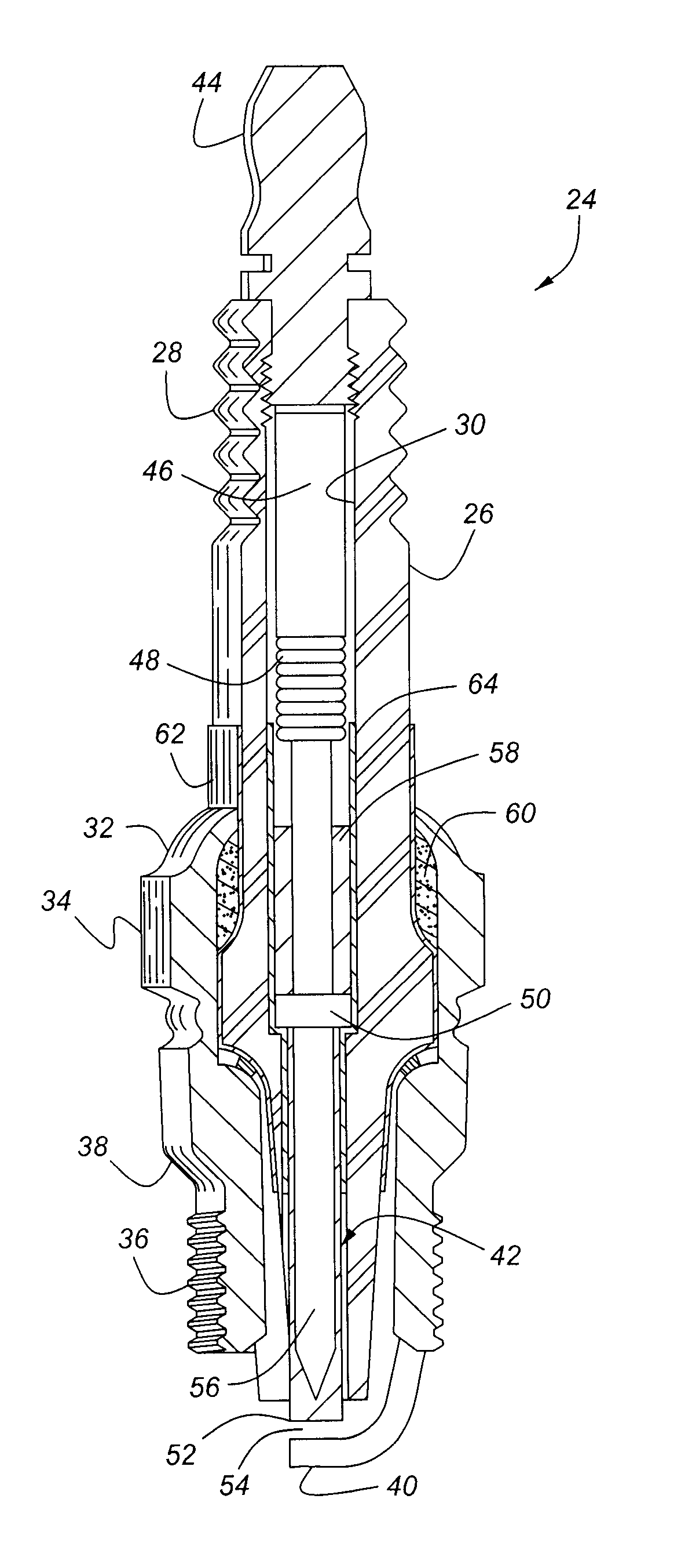
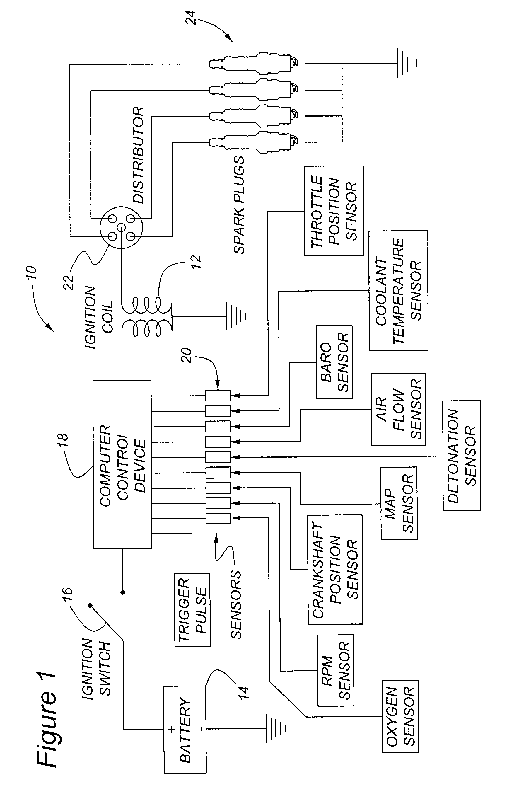
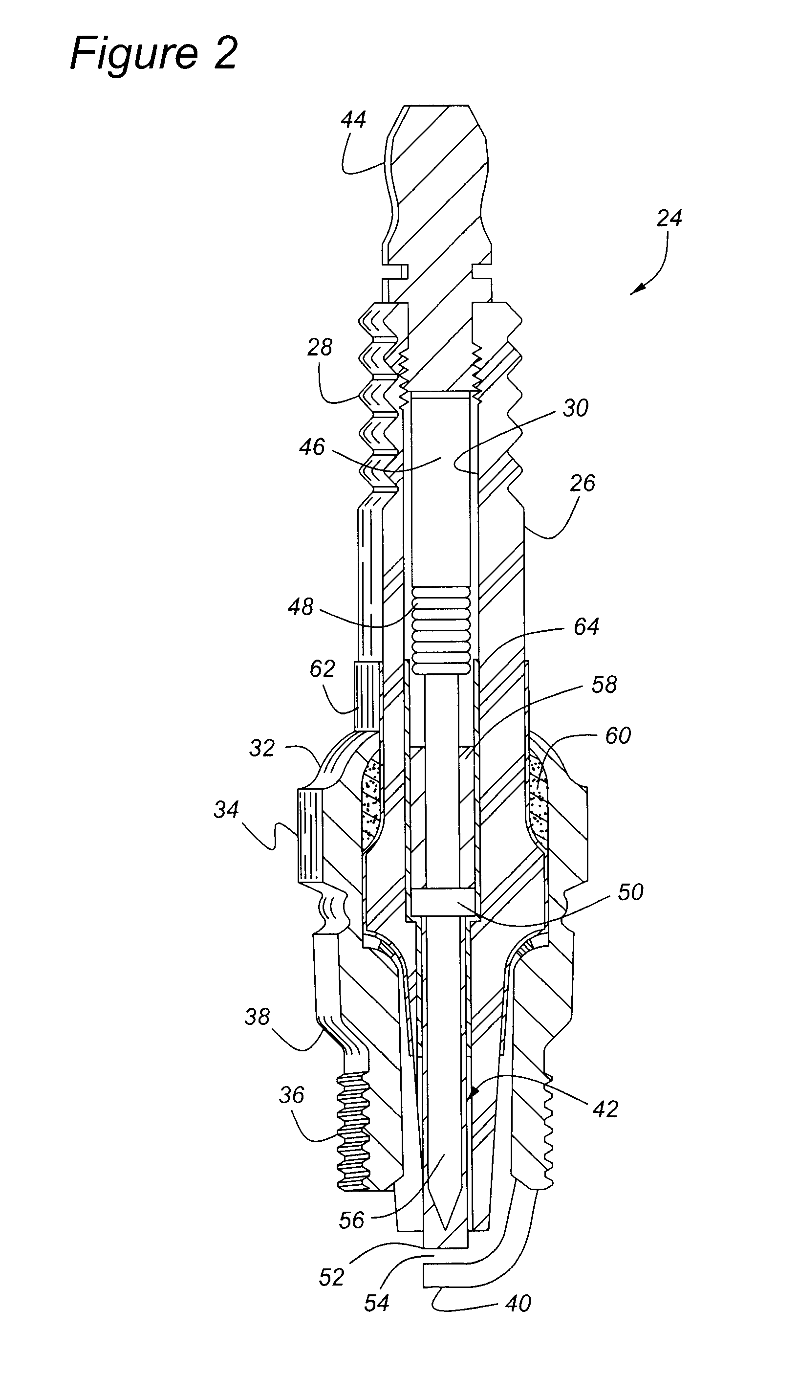
[0023] Referring to the Figures, wherein like numerals indicate like or corresponding parts throughout the several views, an exemplary ignition system for a spark-ignited internal combustion engine is generally shown at 10 in FIG. 1. The ignition system 10 can be of any known type, including the standard ignition system with contact points, a breakerless electronic ignition system, a capacitor discharge ignition system, or the like. In the example of FIG. 1, a computer controlled ignition system is depicted, whose primary purpose is to provide a timed electrical discharge of sufficient energy to ignite a compressed air / fuel mixture in the individual cylinders of an internal combustion engine. The voltage needed to produce this electrical discharge is most often generated by means of an auto-transformer where the current in the primary of an ignition coil 12 is interrupted at the desired time of ignition. This is accomplished by a circuit in which the relatively low voltage in a batt...


PUM


Abstract

A spark plug (24) is used in an ignition system (10) of the type for creating a precisely timed spark to ignite an air/fuel mixture in an internal combustion engine. The spark plug (24) is provided with an integrated capacitor feature to increase the intensity of its spark. The capacitor feature is formed by applying metallic film (62, 64) to the inner (30) and outer surfaces of a tubular insulator (26). The insulator (26), made from an alumina ceramic material, forms a dielectric and sustains an electrical charge when an electrical differential is established between the inner (64) and outer (62) metallic films. The stored electrical charge is discharged with the firing of a spark in the spark gap (54). The inner (64) and outer (62) metallic films can be applied as a paint or ink directly to the surfaces of the insulator (26), or can be mixed with a glazing compound to form conductive coatings simultaneous with the glazing operation. Ganged (62′) or serpentine (62″) micro-plates can be formed within either or both of the inner and outer metallic films to increase the charge-carrying surface area. The metallic film (62, 64) is specially selected from materials that will not migrate into the porous matrix of the ceramic insulator (26). The metallic film (62, 64) is preferably gold, platinum, copper, or a platinum group metal.

Description

CROSS REFERENCE TO RELATED APPLICATIONS [0001] The present application is a Continuation-in-Part of and claims priority to U.S. patent application entitled METALLIC INSULATOR COATING FOR HIGH CAPACITY SPARK PLUG having Ser. No. 11 / 352,708 and filed on Feb. 13, 2006, the entire disclosure of which is hereby incorporated by reference.BACKGROUND OF THE INVENTION [0002] 1. Field of the Invention [0003] The invention relates to an ignition system for a spark-ignited internal combustion engine, and more particularly to a spark plug having high capacitance features. [0004] 2. Related Art [0005] Ignition systems for spark-ignited internal combustion engines rely on a spark plug to produce a spark of sufficiently robust discharge so as to ignite a compressed air / fuel mixture. Often, more efficient ignition can be achieved by increasing the intensity of the spark. [0006] The prior art has taught to incorporate a capacitor into the spark plug to increase the intensity of its spark. Various met...

Claims


Application Information

Patent Timeline
Patent Type & Authority Applications(United States)
IPC IPC(8): H01T13/00F02M57/06H01T13/22
CPCH01T13/20H01T13/38H01T13/36H01T13/40H01T21/02
Inventor LYKOWSKI, JAMES D.
Owner PASSAIC RIVER CO INC
Why Eureka
Try Eureka