Image forming apparatus

Inactive Publication Date: 2007-08-16
RICOH KK
View PDF9 Cites 25 Cited by
  • Summary
  • Abstract
  • Description
  • Claims
  • Application Information

AI Technical Summary

Benefits of technology

[0012] With the foregoing conventional problems in view, it is an object of the present invention to provide an image forming apparatu

Problems solved by technology

The timing of this registration adjustment is at the time of writing, so it is only possible to adjust at scan time intervals of one face of the polygon mirror, so there is a possibility of occurrence of a maximum of one line of color registration error.
However, bending can easily occur in the long direction of long plastic optical elements, in particular in the direction normal to the main scanning direction.
Hence it was very difficult to align between each of the stations with high accuracy scan lines with bending and inclination.
Also, when an actual image is output, curvature is produced at the transfer unit, photoconductive member, and so on, so even if color registration errors are eliminated from the writing unit, color registration errors can still occur.
This type of color registration error can occur while operating, and cause deterioration of the image quality.
However, correction of color registration

Method used


Image

  • Image forming apparatus
  • Image forming apparatus
  • Image forming apparatus

Examples


Example

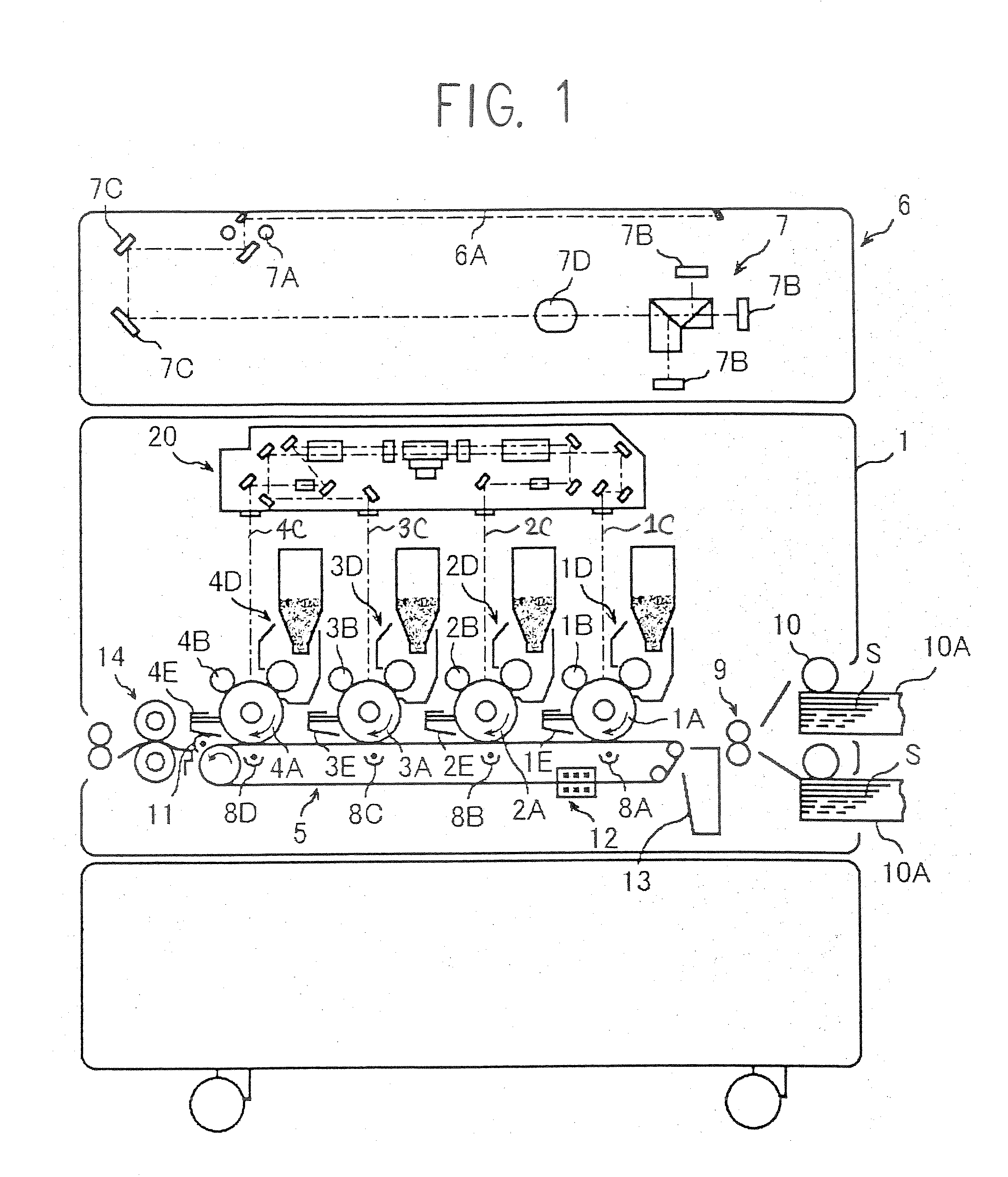
[0039]FIG. 1 shows an outline configuration of an image forming apparatus 1 that is capable of forming color images, that applies a first embodiment of the present invention.

[0040] The image forming apparatus 1 is a photocopier, but may also be a facsimile, printer, a multi-function device that includes a copier and a printer, or another image forming device. If the image forming apparatus 1 is used as a printer or facsimile, image forming processes are carried out based on image signals corresponding to image information received from outside. Also, besides normal sheets used for general copying and the like, image forming can be carried out on recording media S such as OHP sheets, thick sheets such as card, postcards, or envelopes and the like.

[0041] As shown in the figure, the image forming apparatus 1 uses a tandem structure in which a plurality of photoconductive drums (also sometimes simply referred to as “photoconductive members”) 1A, 2A, 3A, 4A are disposed. The plurality ...

Example

Second Embodiment

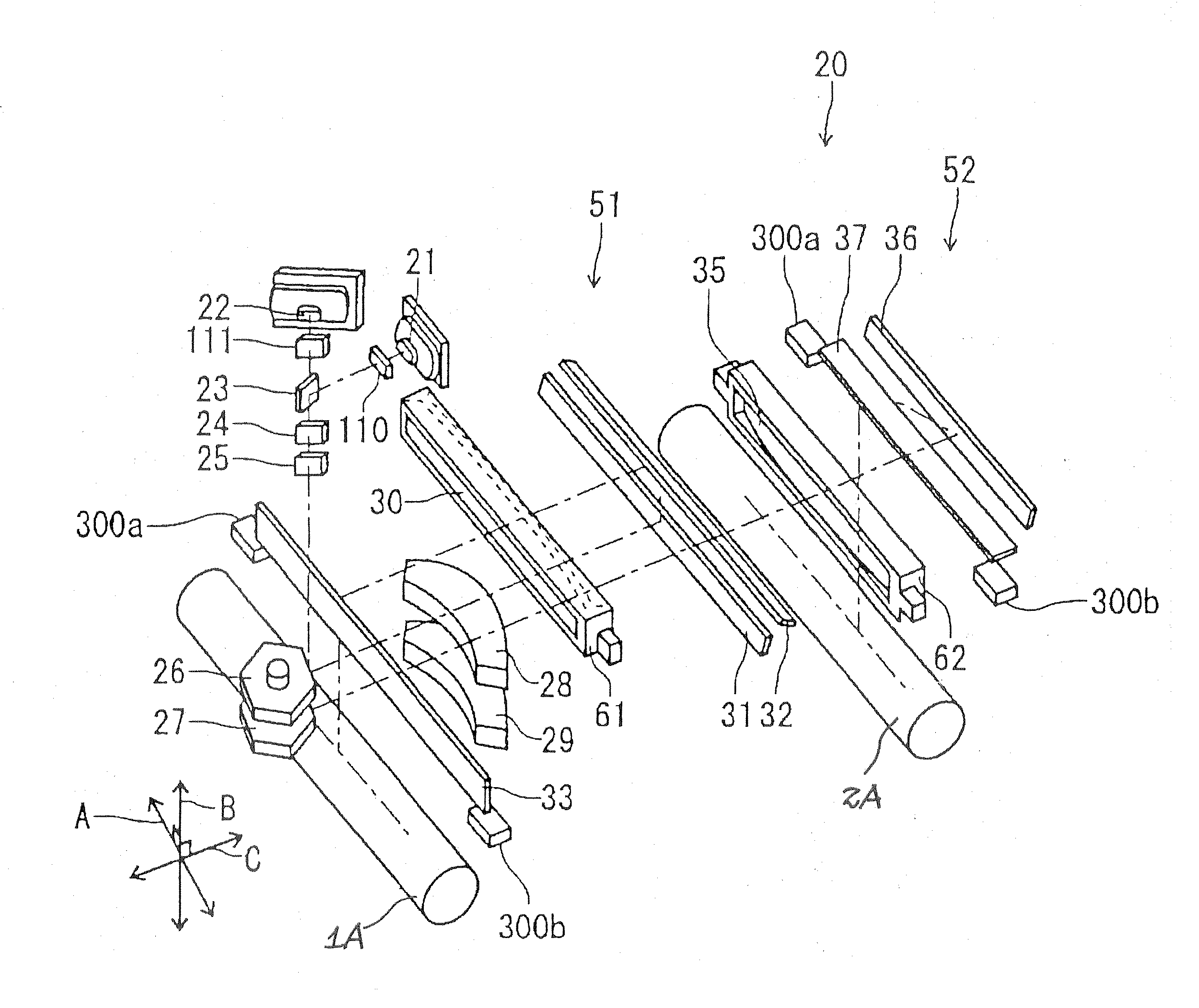
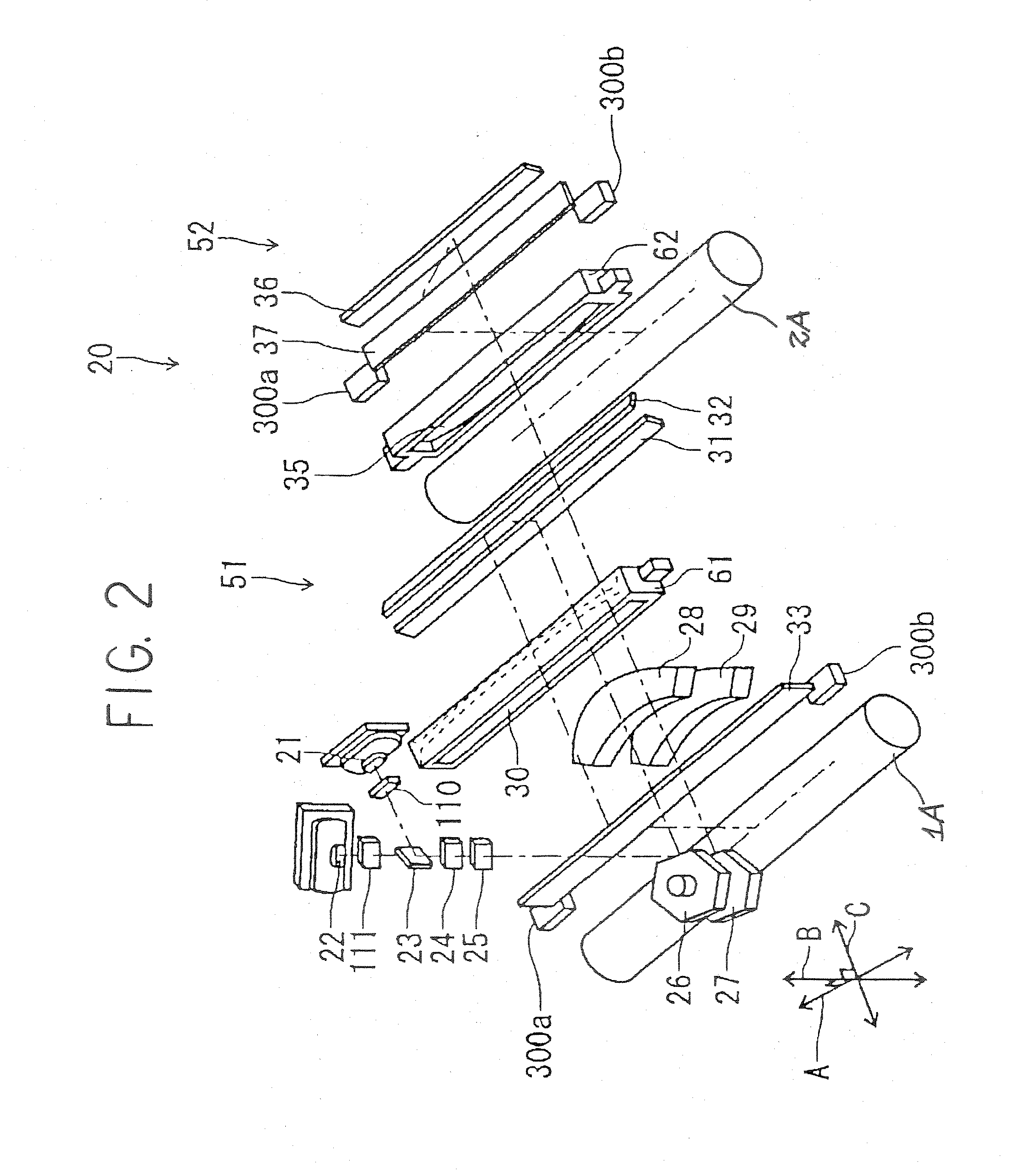
[0106] Next, a second embodiment of the present invention is explained. However, FIGS. 1, 2, 10, and 11, and their associated explanation are also applied to the present embodiment in essentially the same manner, so repetition of their explanation has been omitted. In the following only the differences from the first embodiment and the characteristics of the present embodiment are explained.

[0107] First, in the present embodiment, as stated later, the optical elements 110 and 111 shown in FIG. 2 function as deflecting elements in the sub scanning direction. These sub scanning direction deflecting elements each move the beam position in the sub scanning direction when a voltage is applied to them.

[0108] Next, the method of calculating the bending correction value is explained with reference to FIG. 13.

[0109] The transfer belt 5 rotates in the counterclockwise direction. Color registration error detection patterns 82a, 82b, 82c formed on the photoconductive drum 1...


PUM


Abstract

An image forming apparatus is provided with a light scanning device that directs laser beams emitted from a plurality of laser light sources onto a plurality of photo conductive members via focusing device which includes optical elements and a deflecting device that deflects the beams in a main scanning direction; an image forming device which forms visible images of different colors from images written onto the photoconductive members by the light scanning device; and an intermediate transfer member or a recording sheet transport member capable of carrying the visible images formed on the photoconductive members. When in detection mode, a control device controls the correction of color registration errors between each color forms patterns on an intermediate belt by means of the image forming device, detects the patterns by a color registration error detection sensor, and stores the color registration error correction values obtained from the detection output of the sensor in a memory device. When forming images, the control device reads the color registration error correction values stored in the memory device, and carries out correction in accordance with the correction values via a writing start position correction device which deflects the laser position in the sub scanning direction. Alternatively, when in detection mode, the control device controls the correction of color registration errors between each color forms color registration error detection patterns on a transfer member belt, sets the scan line from among the plurality of scan lines obtained by a pattern detection sensor for the color that passes through the lens that is most distant from the polygon mirror, as the standard scan line, and stores data for the standard scan line and bending correction values for the scan lines of other colors with respect to the standard scan line in the memory device. When forming images, the control device reads the data for the most distant standard scan line and the bending correction values for the scan lines of the other colors stored in the memory device, and carries out correction so that the laser irradiation position coincides with the standard scan line in accordance with the correction values via the sub scan deflecting element.

Description

BACKGROUND OF THE INVENTION [0001] 1. Field of the Invention [0002] The present invention relates to an image forming apparatus including a light scanning device which directs light beams emitted from a plurality of laser light sources onto photoconductive members via an image focusing device having optical elements and a deflection device which deflects the light in a main scanning direction; an image forming device which forms visible images of different colors from the images written onto a plurality of photoconductive members by the light scanning device; and an intermediate transfer member or recording sheet transport member that can support the visible images formed on the photoconductive members. [0003] 2. Description of the Background Art [0004] In a tandem type image forming apparatus that forms images of each color at the same time using a single polygon motor, registration adjustment is carried out between colors to prevent reduction in image quality due to color registra...

Claims


Application Information

Patent Timeline
IPC IPC(8): B41J2/45
CPCG02B26/123H04N1/0473H04N1/1135H04N1/506H04N2201/0471H04N2201/04793H04N2201/04731H04N2201/04732H04N2201/04755H04N2201/04791H04N2201/04722
Inventor KUSUNOSE, NOBORUBANNAI, KAZUNORIMATSUMAE, IWAOSAKAUE, YOSHINOBU
Owner RICOH KK
Why Eureka
Try Eureka