Writing apparatuses and methods

a technology of writing apparatus and writing method, which is applied in the field of writing apparatus and methods, can solve the problems of inability to achieve, unsatisfactory artifacts, and conventional pattern generators

Active Publication Date: 2007-08-16
MICRONIC LASER SYST AB
View PDF36 Cites 26 Cited by
  • Summary
  • Abstract
  • Description
  • Claims
  • Application Information

AI Technical Summary

Benefits of technology

[0012] Example embodiments describe mechanical, optical and / or calibration methods and apparatuses, which may alone or in combination simultaneously provide increased (e.g., high or relatively high) throughput, resolution and / or image quality on larger (e.g., large, very large or relatively large) workpieces.

Problems solved by technology

The boundaries between them, commonly referred to as butting or stitching boundaries, create undesirable artifacts that may be visible in the final pattern.
Conventional pattern generators, however, are unable to do so because merely scaling up conventional pattern generation techniques fails to achieve the required error control.
Moreover, the drum plotter of FIG. 1D includes only a single exposure head, and each of the drum and the single writing unit are only capable of a single type of movement.
Moreover, the optical system of FIG. 1E includes only a single exposure head, and each of the cylindrical workpiece and the single optical writing unit are only capable of a single type of movement.
This photo detector, however, only detects quantity of light from the single optical writing unit.
However, this may require a larger number of optical channels and / or lenses, which may increase cost and / or complexity of the pattern generator.
However, controlling mechanical motion and / or vibration may be more difficult as stage speed increases.
For example, an increase in speed and mass along with a decrease in application time may result in greater vibrations and / or resonances at higher frequencies in the mechanical structures.
In addition, control and / or mechanical systems may not settle properly before writing a new stripe.
Moreover, increased speed, vibration and / or a number of optical channels may increase cost and / or complexity of conventional pattern generators.

Method used


Image

  • Writing apparatuses and methods
  • Writing apparatuses and methods
  • Writing apparatuses and methods

Examples


Embodiment Construction

[0075] Example embodiments are described with reference to the figures. These example embodiments are described to illustrate the present invention, not to limit its scope, which is defined by the claims. Those of ordinary skill in the art will recognize a variety of equivalent variations on example embodiments described as follows.

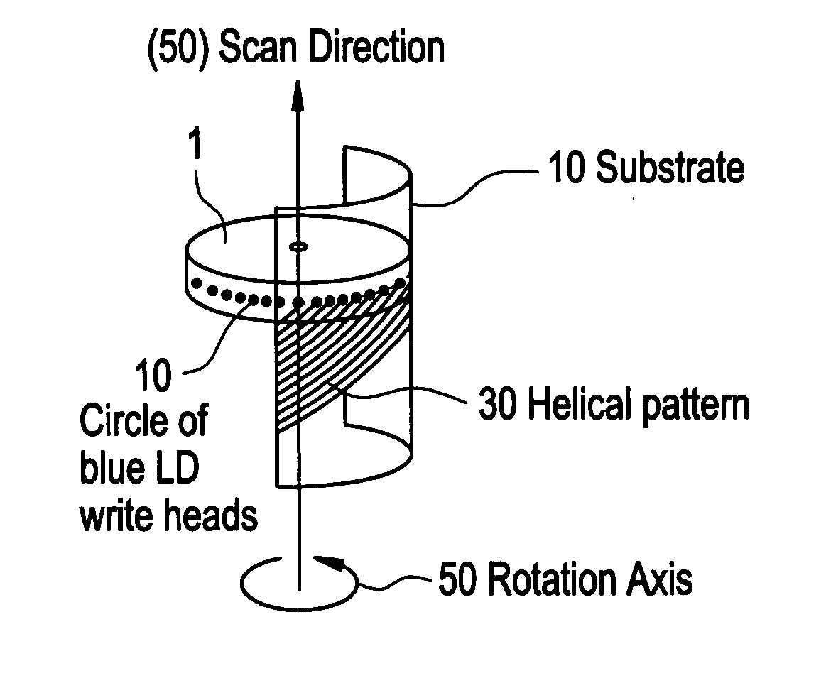
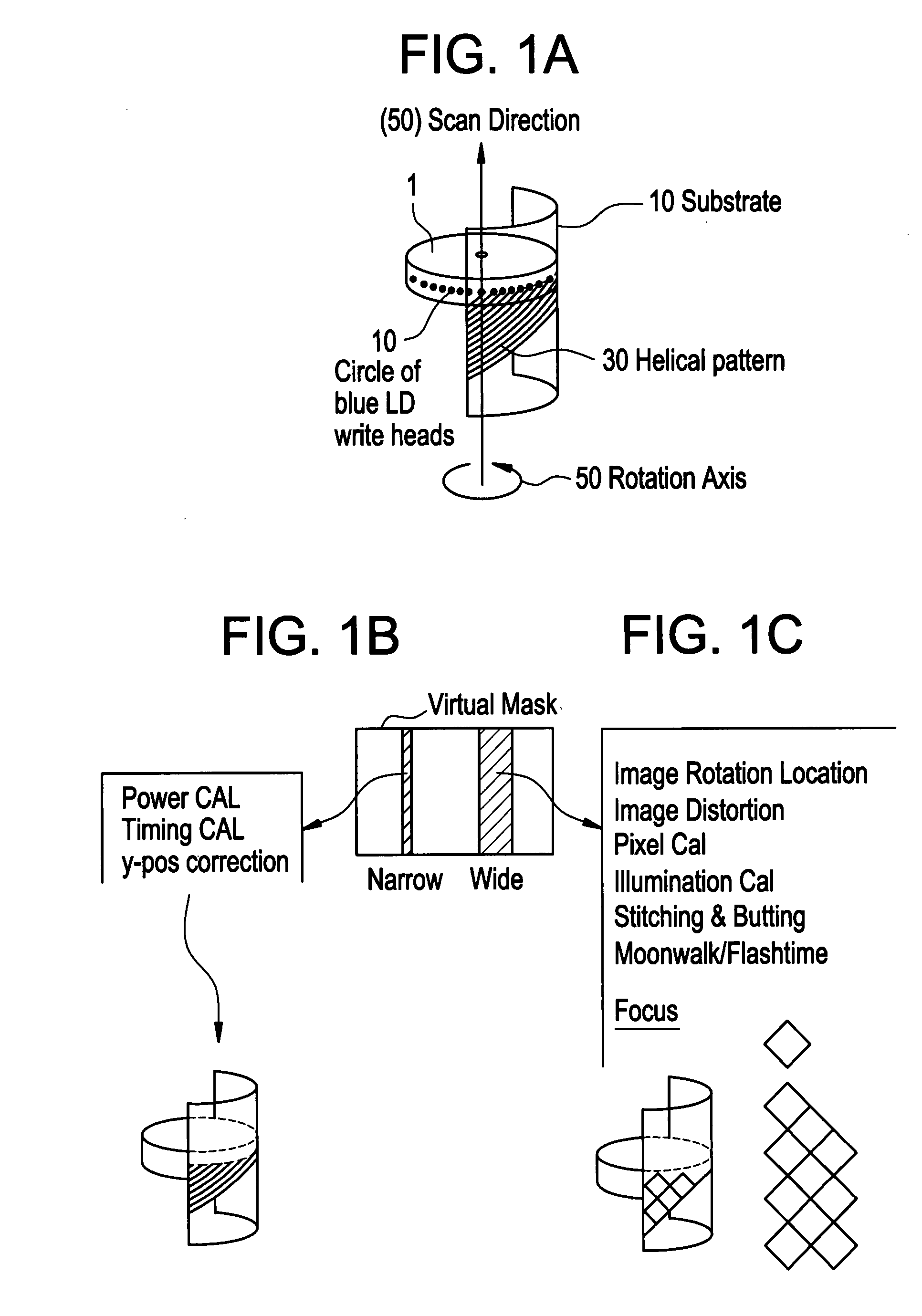
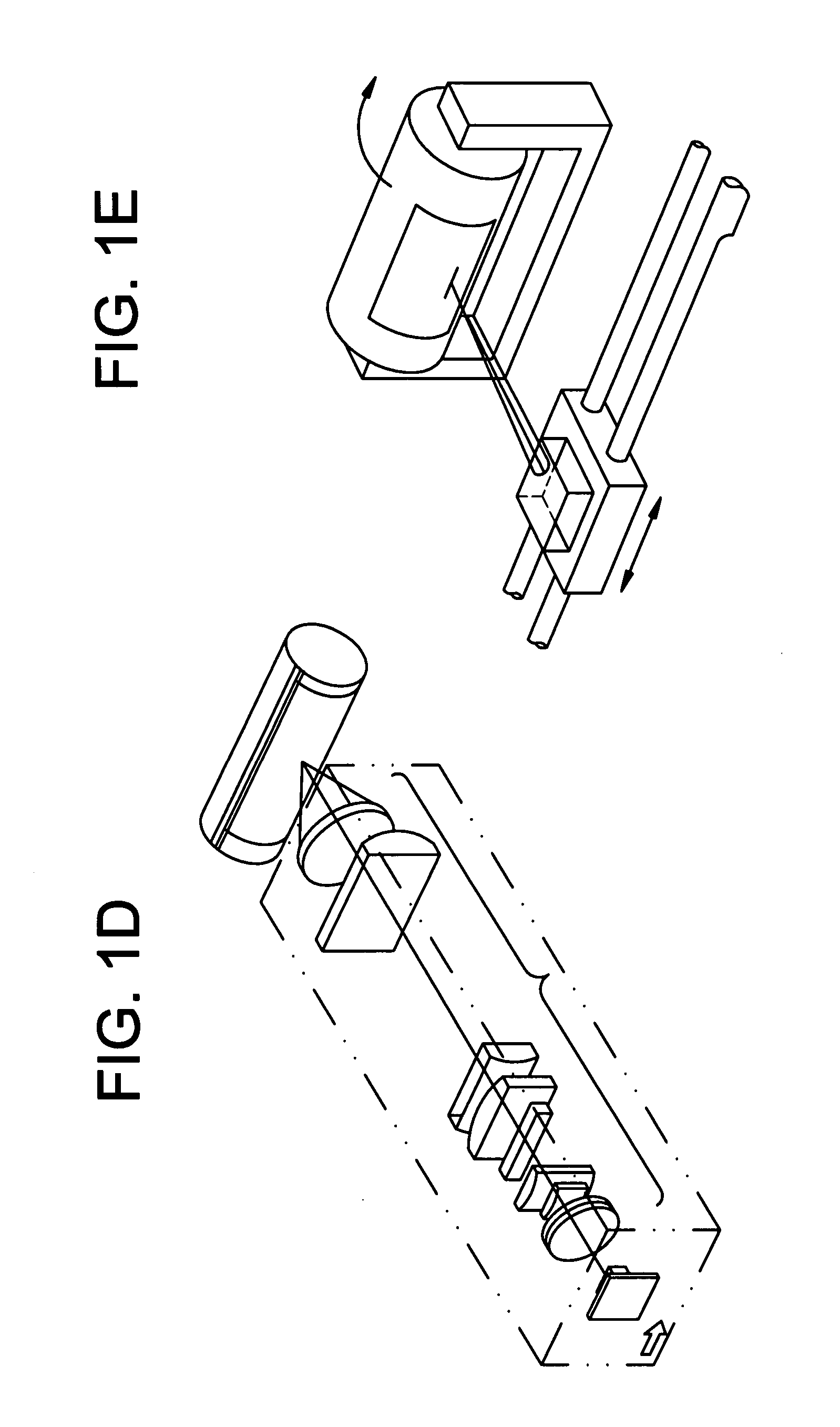
[0076] In at least some examples embodiments, a rotor scanner may be in the form of a ring. In this example, each of a plurality of optical writing units may be arranged and configured to emit electromagnetic radiation in the form of at least one laser beam. The laser beams may be emitted in at least two directions. In at least some examples embodiments, the laser beams may be emitted in at least two parallel directions. In at least some examples embodiments, the laser beams may be emitted in a radial direction inward toward a workpiece arranged on a cylindrical holder positioned inside the ring-shaped rotor scanner.

[0077] In at least some examples embo...


PUM


Abstract

Patterns are written on workpieces, such as, glass sheets and / or plastic sheets used in, for example, electronic display devices such as LCDs. The workpiece may be larger than about 1500 mm may be used. An optical writing head with a plurality of writing units may be used. The workpiece and the writing head may be moved relative to one another to provide oblique writing.

Description

PRIORITY STATEMENT [0001] This non-provisional U.S. patent application claims priority to provisional U.S. patent application Ser. Nos. 60 / 730,009, filed on Oct. 26, 2005 and 60 / 776,919, filed on Feb. 28, 2006, the entire contents of both of which are incorporated by reference.BACKGROUND [0002] Conventional pattern generation systems for patterning large workpieces also create the pattern in stripes, swaths or rectangles. The boundaries between them, commonly referred to as butting or stitching boundaries, create undesirable artifacts that may be visible in the final pattern. U.S. Pat. No. 5,495,279, the entire contents of which are incorporated herein by reference, illustrates a conventional method and apparatus for exposing substrates. [0003] Extremely high throughput, for example in the range of about 0.05 m2 / s through about 0.2 m2 / s, combined with the large size of the workpieces, (e.g., in a range of about 5 m2 through 10 m2, and even 20 m2 or more), high optical resolution (e....

Claims


Application Information

Patent Timeline
Patent Type & Authority Applications(United States)
IPC IPC(8): B41J2/435
CPCB41J2/442H05K3/0082G02F2203/12G03F7/2053G03F7/24G03F7/70275G03F7/70291G03F7/70358G03F7/70366G03F7/70383G03F7/70391G03F7/704G03F7/70783G03F7/70791H04N1/06H04N1/0607H04N1/0628H04N1/0664H04N1/0671H05K1/0393G02F1/1303G03F7/70425G03F7/20G01D15/14B41J2/47
Inventor SANDSTROM, TORBJORN
Owner MICRONIC LASER SYST AB
Why Eureka
Try Eureka