Heat sink

a heat sink and heat sink technology, applied in the field of heat sinks, can solve the problems of increasing the weight of the heat sink, increasing noise, and affecting the heat dissipation effect, so as to achieve sufficient heat exchange, effectively dissipate the heat of the fin unit, and enhance the turbulence on the surface of the fin.

Inactive Publication Date: 2007-08-16
HON HAI PRECISION IND CO LTD +1
View PDF11 Cites 17 Cited by
  • Summary
  • Abstract
  • Description
  • Claims
  • Application Information

AI Technical Summary

Benefits of technology

[0008] The guiding member formed in each fin of the heat sink can guide the distribution and flow direction of the airflow whilst simultaneously enhancing the turbulence on the surface of the fin. Thus the fin unit can have a sufficient heat exchange with the airflow, effectively dissipating the heat of the fin unit that is absorbed from the heat-generating electronic device to the surrounding environment.

Problems solved by technology

However, this increases the weight of the heat sink, which conflicts with the requirement for light weight and compactness.
This way may avoid increasing the volume of heat sink 1, however, reducing the spacing between two adjacent fins of the fin unit 2 will increase the flow resistance, which not only influences the heat dissipation effect but also increases the noise.
Therefore, the airflow flowing through the fin unit cannot sufficiently assist heat dissipation from a heat-generating electronic device.
Accordingly, heat dissipation effectiveness of the conventional heat sink 1 is limited.

Method used


Image

  • Heat sink
  • Heat sink
  • Heat sink

Examples


Embodiment Construction

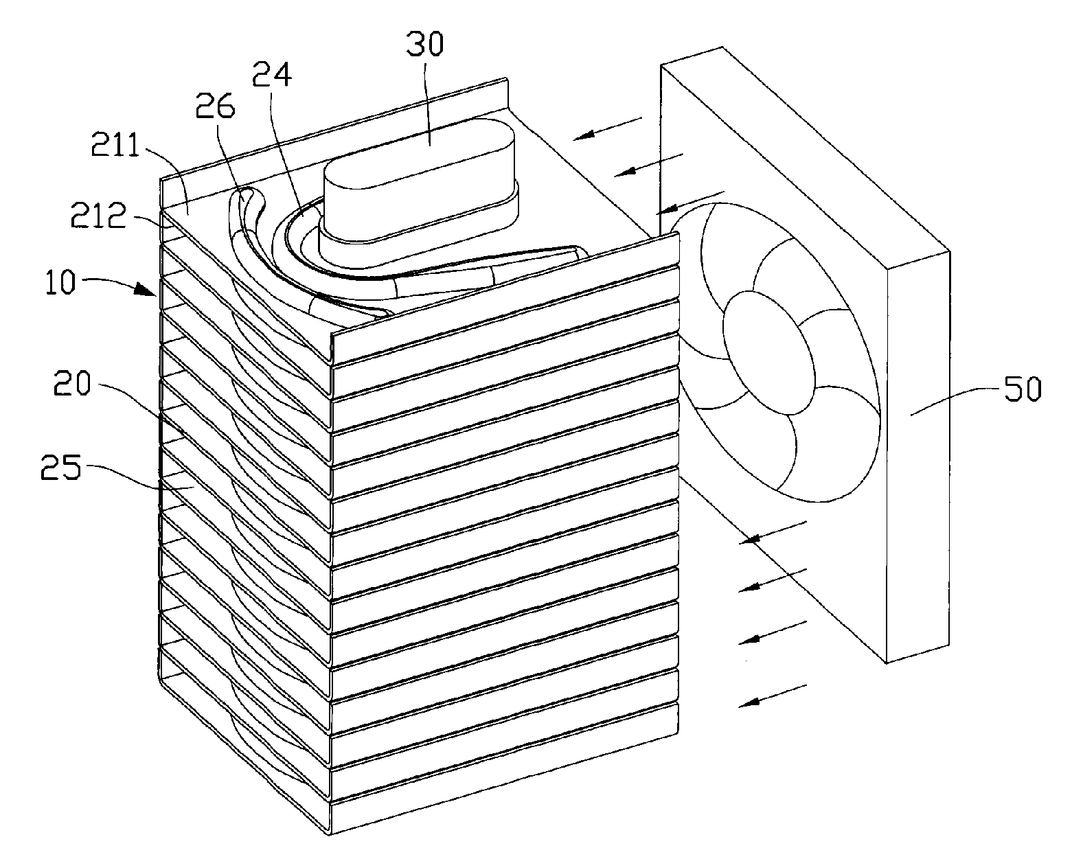
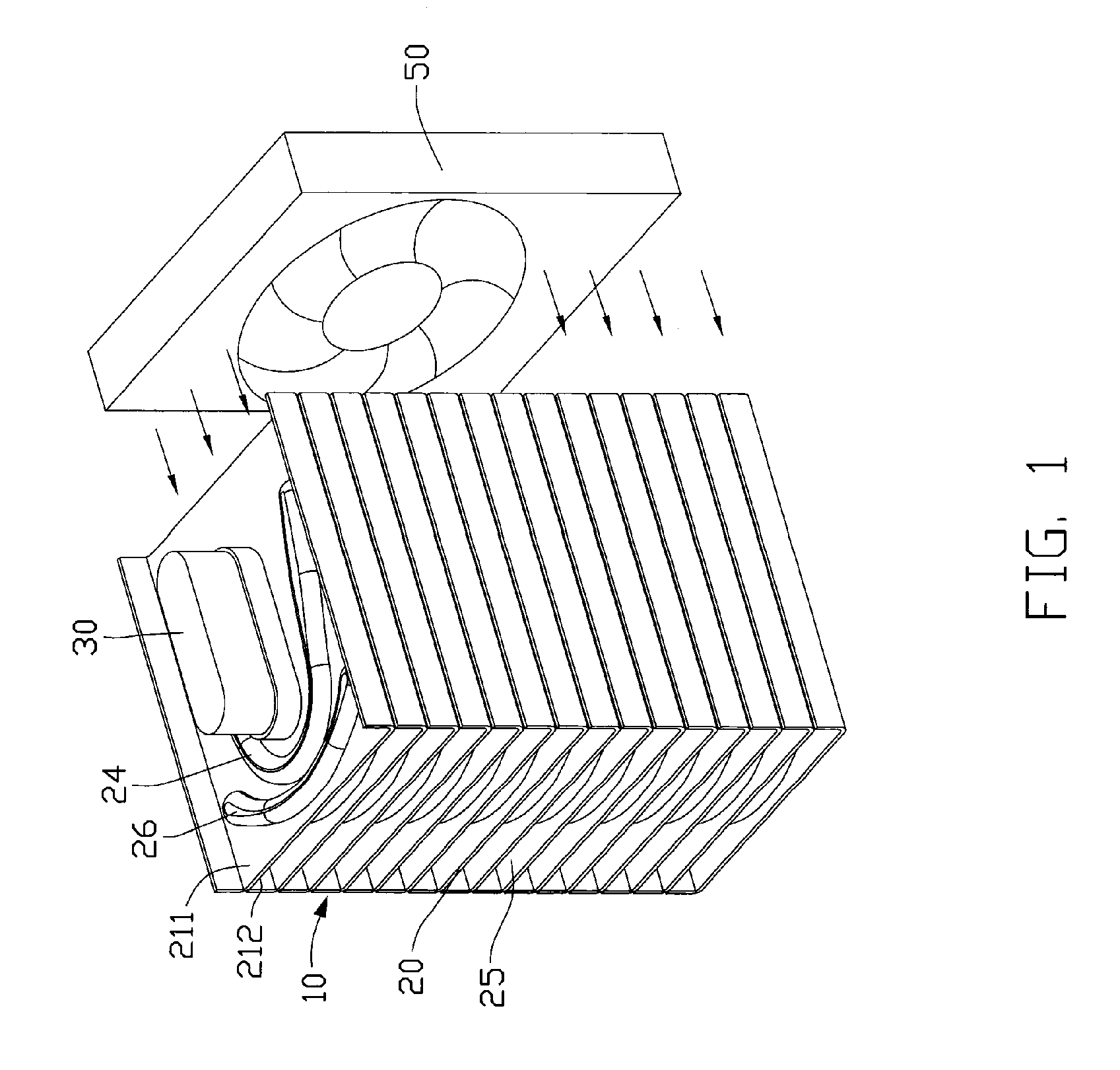
[0015] Referring to FIG. 1, a heat sink comprises a fin unit 10, and a heat pipe 30 extending through the fin unit 10. The heat pipe 30 has an evaporating section (not labeled) for thermally connecting with a heat source, for example, a central processing unit (CPU, not shown). A cooling fan 50 is arranged at a side of the fin unit 10 for generating an airflow towards the fin unit 10 as indicated by arrows.

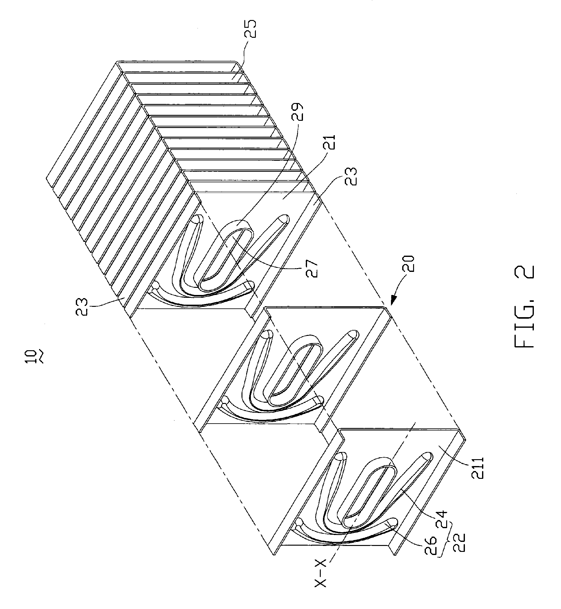
[0016] Referring to FIGS. 2-4, the fin unit 10 comprises a plurality of stacked fins 20 parallel to each other. Each fin 20 has a main body 21 which has a reference surface 211 and a base surface 212, and two hems 23 bent from two opposite side edges of the main body 21. Distal edges of the hems 23 of each fin 20 contact with the base surface 212 of an adjacent fin 20, and the height of these hems 23 is thus equal to the distance between the two neighboring fins 20. A flow channel 25 is formed between each two neighboring fins 20 to channel the airflow generated by the fan 50. A ...


PUM


Abstract

A heat sink includes a plurality of fins parallel to each other, and one heat pipe extending through these fins. A flow channel is formed between each pair of neighboring fins for channeling an airflow generated by an electric fan. A guiding member having a curved shape is arranged around the through hole for guiding the airflow flowing to the heat pipe. A space formed and surrounded by the guiding member is a tapered space, which narrows gradually along the direction of the airflow so as to guide the airflow flowing to the heat pipe.

Description

FIELD OF THE INVENTION [0001] The present invention relates generally to a heat sink, and in particular to a heat sink with improved fin structure for achieving a high heat-dissipation efficiency. DESCRIPTION OF RELATED ART [0002] With the advance of large scale integrated circuit technology, and the wide spread use of computers in all trades and occupations, in order to meet the required improvement in data processing load and request-response times, high speed processors have become faster and faster, which causes the processors to generate redundant heat. Redundant heat which is not quickly removed will have tremendous influence on the system security and performance. Usually, people install a heat sink on the central processor to assist its heat dissipation, whilst also installing a fan on the heat sink, to provide a forced airflow to increase heat dissipation. [0003]FIG. 5 shows a conventional heat sink 1. The heat sink 1 comprises a fin unit 2, a heat pipe 4 extending through ...

Claims


Application Information

Patent Timeline
Patent Type & Authority Applications(United States)
IPC IPC(8): H05K7/20
CPCF28D15/02F28D2021/0029F28F2250/08F28F1/30F28F13/06F28D2021/0031F28D15/0275
Inventor HWANG, CHING-BAIMENG, JIN-GONG
Owner HON HAI PRECISION IND CO LTD
Why Eureka
Try Eureka