Adaptive modulation and coding

a technology applied in the field of adaptive modulation and coding methods and apparatuses, can solve the problems of poor performance at lower mcs levels and does not provide a satisfactory solution, and achieve the effect of lowering the target error ra

Inactive Publication Date: 2007-08-16
FUJITSU LTD
View PDF19 Cites 4 Cited by
  • Summary
  • Abstract
  • Description
  • Claims
  • Application Information

AI Technical Summary

Benefits of technology

[0036] For example, a ratio of the downward amount to the upward amount may be dependent upon a target error rate of the received signal. This target error rate is a measure of the expected success in receiving the signal. In one embodiment, the ratio of the downward amount to the upward amount is made equal to the ratio of the number of times the signal is received unsuccessfully to the number of times the signal is received successfully, i.e. the target error rate divided by 1 minus that error rate. In this way, the lower the target error rate the lower the ratio between the downward amount and the upward amount.
[0037] In one embodiment the downward amount and / or the upward amount is / are dependent upon a difference between the threshold value and the signal transmission quality. For example, the or each amount increases as the difference decreases. This has the effect of magnifying the adjustment amounts near to the threshold value, whilst limiting any adjustments further away from the threshold value.

Problems solved by technology

The method proposed by NEC / Telecom MODUS changes the thresholds as the operating conditions change but the method does not provide a satisfactory solution as it increases or decreases the threshold each time an ACK or NACK message is received, i.e. every frame.
This appears to result in relatively poor performance at lower MCS levels for path conditions in which there is effectively a single dominant path, for example in open countryside.

Method used


Image

  • Adaptive modulation and coding
  • Adaptive modulation and coding
  • Adaptive modulation and coding

Examples


Embodiment Construction

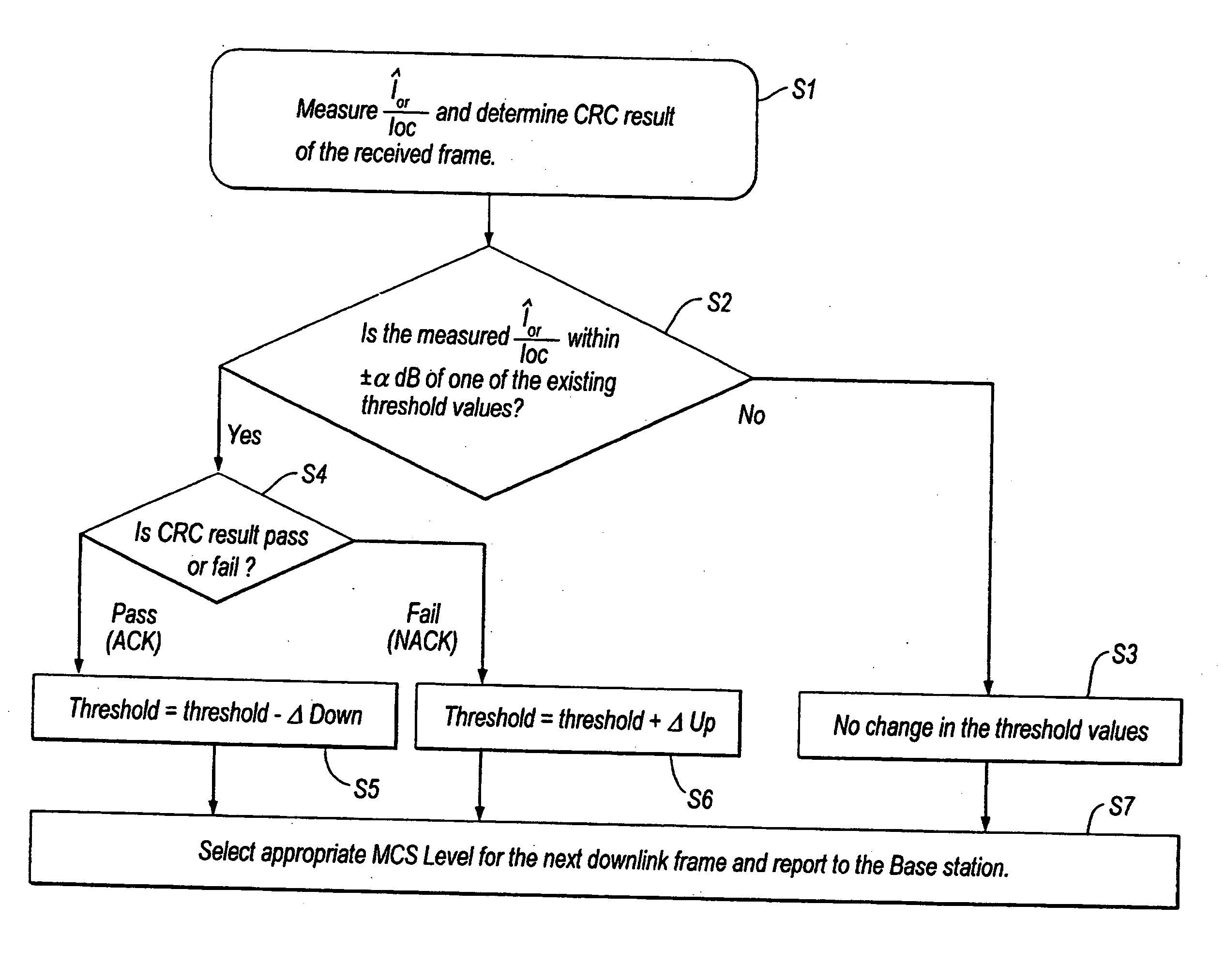
[0068]FIG. 8 is a flowchart for use in explaining an AMCS method according to a first embodiment of the present invention. In this embodiment, the UE selects the appropriate MCS level for each frame of the downlink signal and reports the selected level to the base station.

[0069] In this example, the method is used to adapt the MCS level of a downlink packet access signal in an HSDPA system.

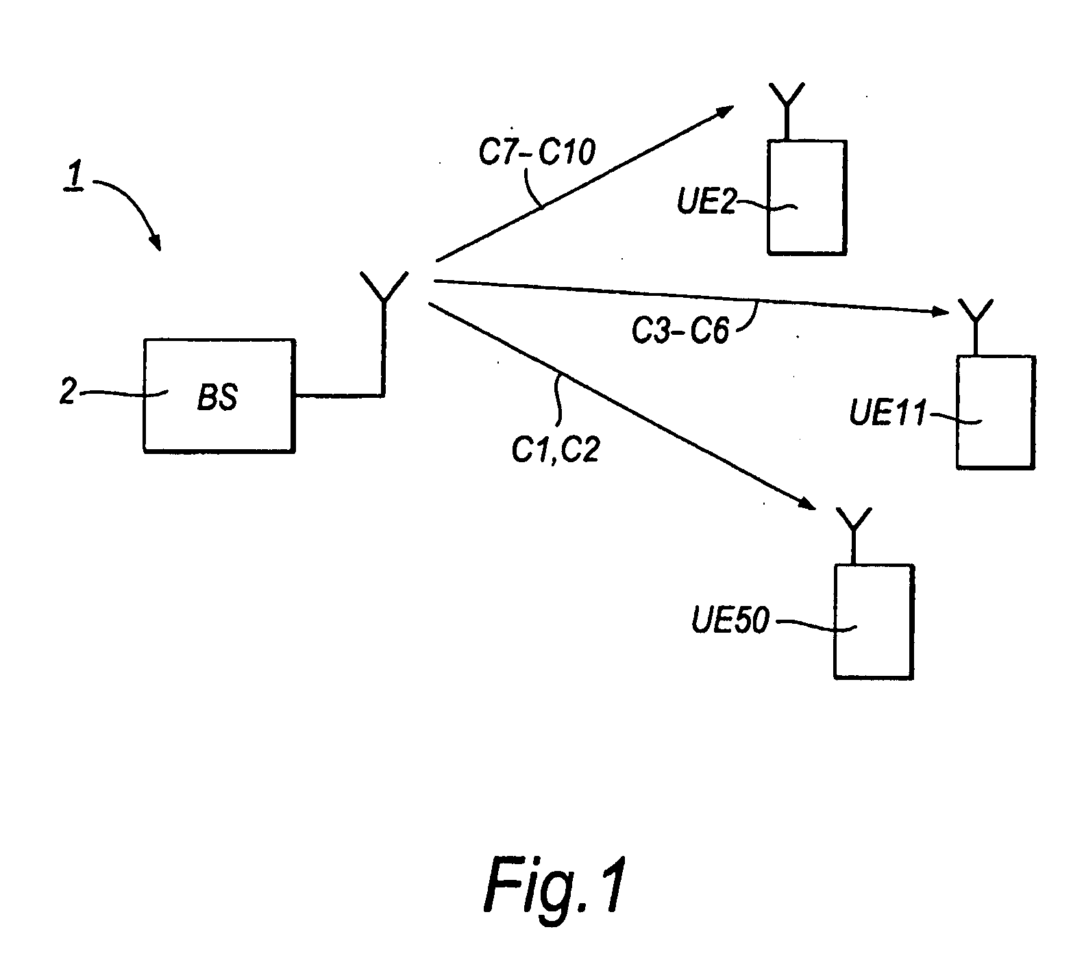
[0070]FIG. 9 is a schematic view for explaining signalling in the first embodiment.

[0071] For downlink signalling, four channels are used. A common pilot channel (CPICH) is used to broadcast a signal to all UEs in the cell served by the base station, in order to enable each UE to measure a downlink channel quality based on the CPICH signal. A high-speed downlink shared channel HS-DSCH is used to transmit packet data to a UE. A high-speed shared control channel HS-SCCH is used to carry transport format and resource related information (TFIR). This TFIR is, for example, 8 bits and includes inform...


PUM


Abstract

A base station, for use in a wireless communication system, includes a report receiving unit operable to receive from a user equipment. of the system a report of a downlink received signal quality produced by the user equipment. The report receiving unit includes a unit operable to receive a report of a measuring received signal quality or a report of a selected modulation and coding scheme to the transmitter.

Description

CROSS-REFERENCE TO RELATED APPLICATIONS [0001] This application is a divisional of U.S. application Ser. No. 10 / 629,386, filed Jul. 29, 2003, which is a continuation of Great Britain Application No. 0217654.3, filed Jul. 30, 2002, which are hereby incorporated by reference herein in their entirety.BACKGROUND OF THE INVENTION [0002] 1. Field of the Invention [0003] The present invention relates to adaptive modulation and coding methods and apparatus for use, for example, in wireless communication systems. [0004] 2. Description of the Related Art [0005]FIG. 1 shows parts of a wireless communication system 1. The system includes a plurality of base stations 2, only one of which is shown in FIG. 1. The base station 2 serves a cell in which a plurality of individual users may be located. Each user has an individual user equipment (UE). Only the user equipments UE2, UE11 and UE50 are shown in FIG. 1. Each UE is, for example, a portable terminal (handset) or portable computer. [0006] As is...

Claims


Application Information

Patent Timeline
Patent Type & Authority Applications(United States)
IPC IPC(8): H04Q7/00H04L27/18H04B1/7075H04B7/26H04L1/00H04L1/18H04L27/00H04L27/34H04W28/18
CPCH04B1/70755H04L1/0003H04L1/0009H04L1/0021H04W28/18H04L1/0026H04L1/0031H04L1/1812H04L1/0025
Inventor AWAD, YASSIN ADENNAKAMURA, MICHIHARU
Owner FUJITSU LTD
Why Eureka
Try Eureka