
Ferrofluid Centered Voice Coil Speaker

a voice coil and speaker technology, applied in the field of audio speakers, can solve the problems of early speaker failure, affecting sound quality, and causing undesirable stresses on the suspension system, and achieve the effect of low volatility and lower magnetization

Active Publication Date: 2007-08-16
FERROTEC MATERIAL TECH CORP
View PDF6 Cites 21 Cited by
  • Summary
  • Abstract
  • Description
  • Claims
  • Application Information

AI Technical Summary

Benefits of technology

[0015]It is an object of the present invention to provide an audio speaker that uses ferrofluid for centering a voice coil without the need for ferrofluid equalizing vent openings. It is another object of the present invention to provide an audio speaker that uses ferrofluid for centering a voice coil without the need for ferrofluid equalizing vent openings or the use of a mechanical centering device such as a spider. It is a further object of the present invention to provide an audio speaker that uses a ferrofluid for centering a voice coil having low volatility and lower magnetization than previously required for high excursion woofers.
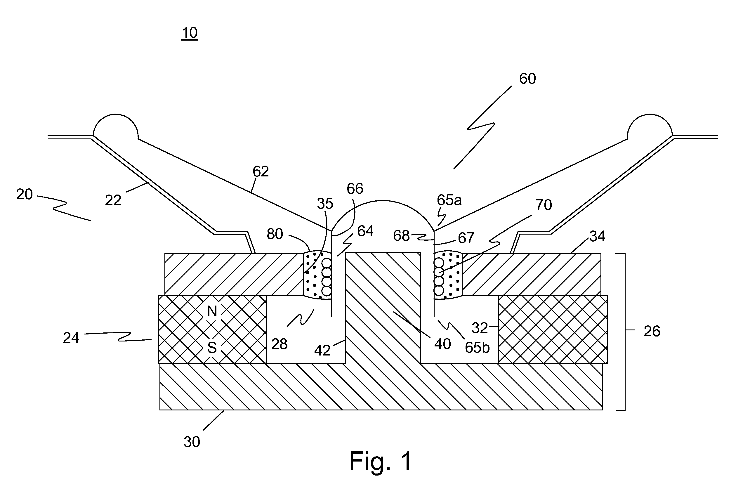
[0017]The major features of the present invention are the placement of magnetic fluid on only one side of the voice coil to create a centering force to keep the voice coil centered in the annular gap and the lack of the requirement for a mechanical centering device such as a spider. The magnetic fluid is positioned in the space on the side of the voice coil having the higher magnetic flux density. Another important aspect of the present invention is the requirement to prevent the migration of the magnetic fluid from one side of the voice coil to the other.
[0018]It should be noted that the magnetic gap or air gap may be thought of as having a gap portion of higher magnetic field that diminishes in strength across the gap to a gap portion of lower magnetic field. Magnetic fluid will naturally reside in a gap portion of higher magnetic field. The magnetic fluid, however, will migrate to a gap portion of lower magnetic field located at the corners of the pole piece that is situated in the lower magnetic field unless the gap portions are separated. The tubular form of the voice coil of the present invention is structured to maintain gap portion separation and prevent magnetic fluid migration.
[0025]It is also important that the magnetic fluid, once positioned in the space on the side of the voice coil having the greater magnetic flux density, is prevented from migrating to the other side of the voice coil. One way to prevent magnetic fluid migration is to lengthen the tubular form that makes up the voice coil. The length of the tubular form should be sufficient so that the magnetic fluid cannot migrate around the end of the voice coil during the voice coil's greatest excursion as it oscillates. In addition, where vent openings are incorporated through the wall of the tubular form to equalize air pressure, the vent openings must be positioned so that the magnetic fluid does not contact the edge of the vent openings during the voice coil's greatest excursion as it oscillates. Allowing the magnetic fluid to migrate through the vent openings would also defeat the advantage of maximum centering force provided by the present invention.

Problems solved by technology

Any scraping of the voice coil against the sides of the air gap causes humming and distortion, which affects sound quality.
Additionally, scraping creates undesirable stresses on the suspension system as well as removal of the insulation from the coil windings.
This leads to early speaker failure.
The inclusion of a spider requires additional space in the speaker, which is not available in audio speakers such as tweeters and very small full range speakers.
Unfortunately, the use of ferrofluid in the air gap causes other problems.
If the pressure builds up to a point where it exceeds the pressure capacity of the ferrofluid O-ring seal, the air bursts through the seal and relatively large amounts of the ferrofluid may then be blown or flow out of the gap.
Other problems that arise when using ferrofluid in the air gap around the voice coil involve equalization of the amount of ferrofluid on both sides of the voice coil (because filing the entire gap can be problematic) and equalization of the air pressure under the dust cap of the voice coil.

Method used


Image

  • Ferrofluid Centered Voice Coil Speaker
  • Ferrofluid Centered Voice Coil Speaker
  • Ferrofluid Centered Voice Coil Speaker

Examples


Embodiment Construction

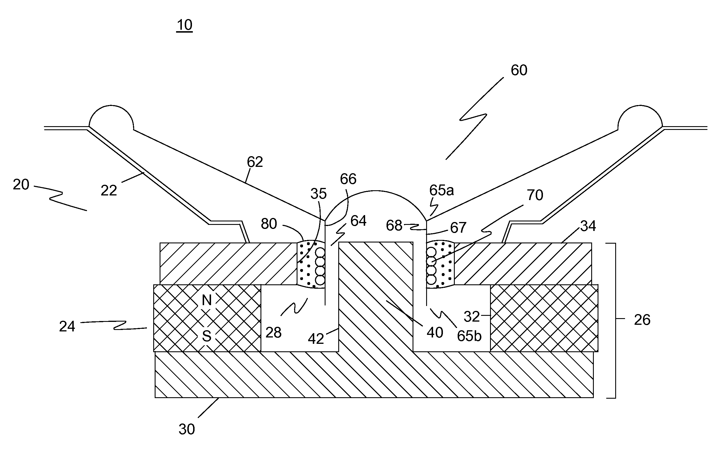
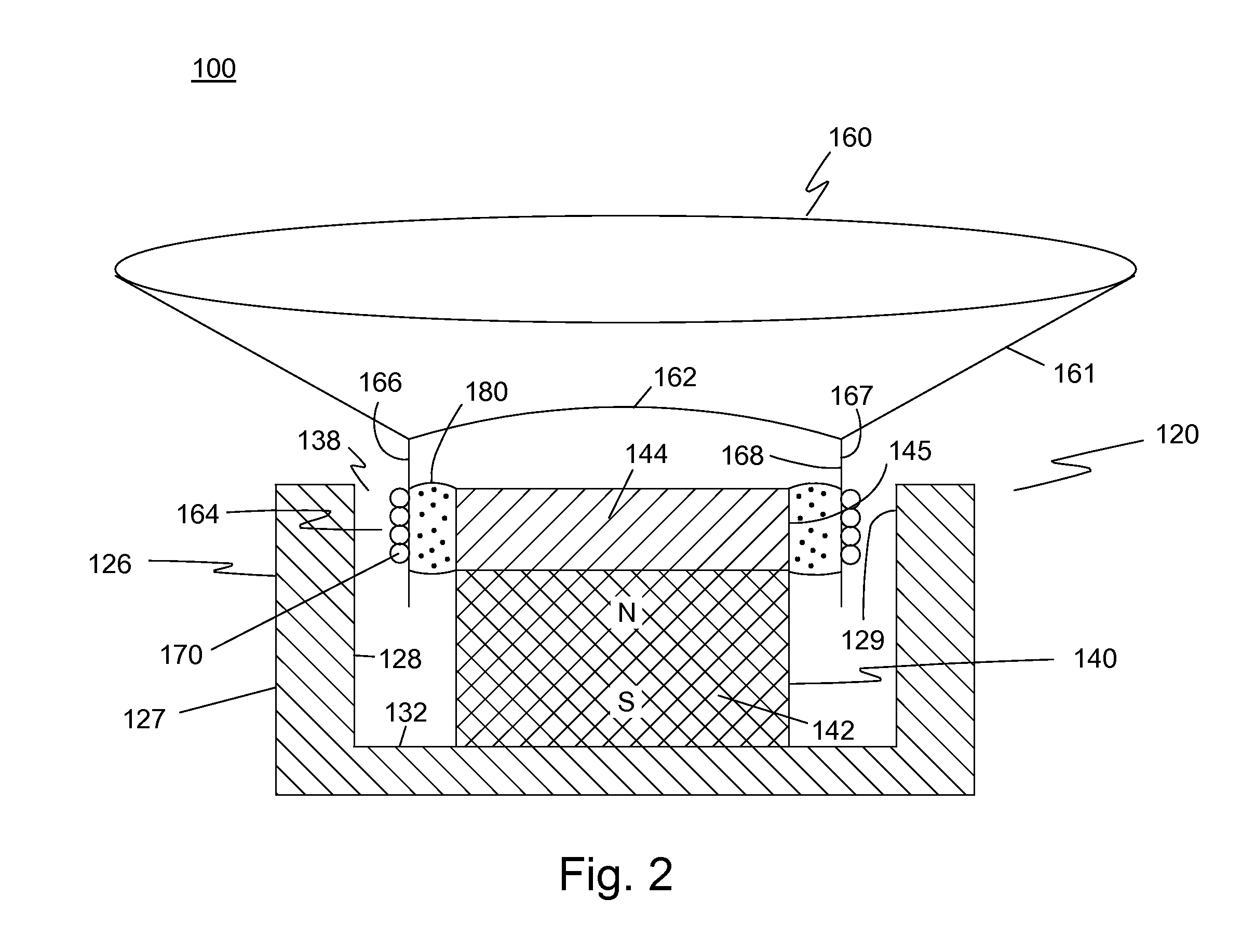
[0029]The preferred embodiment of the present invention is illustrated in FIGS. 1-2. FIG. 1 shows a simplified cross-section of one embodiment of an audio speaker 10. Audio speaker 10 includes a driver unit 20, a vibration system 60 and magnetic fluid 80. Driver unit 20 includes a support frame 22 and a central portion 24. Central portion 24 includes a magnetic structure 26 defining an annular gap 28 around a central magnetic post 40.

[0030]In this embodiment, magnetic structure 26 is an assembly having a base plate 30 with the central magnetic post 40, an annular permanent magnet 32 and an annular top plate 34. Base plate 30 and central magnetic post 40 may be made from a single piece of magnetic material or may be two or more pieces integrally joined. Annular permanent magnet 32 is axially polarized where one face of magnet 32 has one polarity and the other face of magnet 32 has the opposite polarity. Magnet 32 is sandwiched between base plate 30 and annular top plate 34.

[0031]Cent...


PUM


Abstract

An audio speaker has a driver unit having a support frame with a central portion forming a magnetic structure defining an annular gap around a central magnetic post, a vibration system having a diaphragm and a voice coil, the voice coil is attached to one side of the diaphragm where the vibration system is fixed to the support frame and where the voice coil is movably mounted in the annular gap, and a magnetic fluid disposed in the annular gap only in a space between one side of the voice coil and a surface of the annular gap having a higher magnetic flux density.

Description

[0001]This application claims the benefit of U.S. Provisional Patent Application No. 60 / 766,831, filed Feb. 14, 2006.BACKGROUND OF THE INVENTION[0002]1. Field of the Invention[0003]The present invention relates to audio speakers. Particularly, the present invention relates to audio speakers that utilize liquid suspension mechanisms for the voice coils incorporated into audio speakers.[0004]2. Description of the Prior Art[0005]Audio speakers produce audible sounds by displacing air by way of the movement of a diaphragm. The diaphragm is attached to and moves under the control of a voice coil, through which electric currents associated with the sounds to be reproduced are driven. The voice coil is disposed in an annular air gap of a magnetic structure. The magnetic structure includes a permanent magnet that provides radial flux in the air gap. Current through the coil interacts with this radial flux to provide axial forces on the coil and causes displacement of the coil and the attach...

Claims


Application Information

Patent Timeline
IPC IPC(8): H04R9/06
CPCH04R9/027H04R2400/00H04R9/041H04R1/02H04R9/04H04R9/06H04R2201/02H04R2209/024H04R2400/13
Inventor TSUDA, SHIROROSENSWEIG, RONALD E.
Owner FERROTEC MATERIAL TECH CORP
Learn More