Spacer for production of battery pack

a spacer and battery pack technology, applied in the direction of batteries, cell components, cell component details, etc., can solve the problems of reducing affecting the service life of the battery pack, and the possibility of damage or breakage of the fixing tape and the plastic coating, so as to maximize the effect of the provision of the thermistor and the effect of high electrical insulation and high thermal resistan

Active Publication Date: 2007-08-16
LG ENERGY SOLUTION LTD
View PDF1 Cites 27 Cited by
  • Summary
  • Abstract
  • Description
  • Claims
  • Application Information

AI Technical Summary

Benefits of technology

[0022] In the spacer with the above-stated construction, at least one thermistor may be mounted in the vertical through-channel for measuring the temperature of the unit cells. Preferably, the vertical through-channel communicates with the horizontal through-hole. In this structure, it is preferable to locate the thermistor in the region where the vertical through-channel and the horizontal through-hole communicate with each other, whereby th...

Problems solved by technology

Especially, cylindrical secondary batteries, which are used as the unit cells of the battery pack, have great difficulty in maintaining the arrangement structure due to the appearance characteristics thereof.
However, the strength of the fixing tape and the plastic coating is small, and therefore, the possibility is very high that the fixing tape and the plastic coating are damaged or broken.
Consequently, the fixing tape and the plastic coating are not suitable for stably maintaining the arrangement structure of the unit ...

Method used


Image

  • Spacer for production of battery pack
  • Spacer for production of battery pack
  • Spacer for production of battery pack

Examples


Embodiment Construction

[0036] Now, preferred embodiments of the present invention will be described in detail with reference to the accompanying drawings. It should be noted, however, that the scope of the present invention is not limited by the illustrated embodiments.

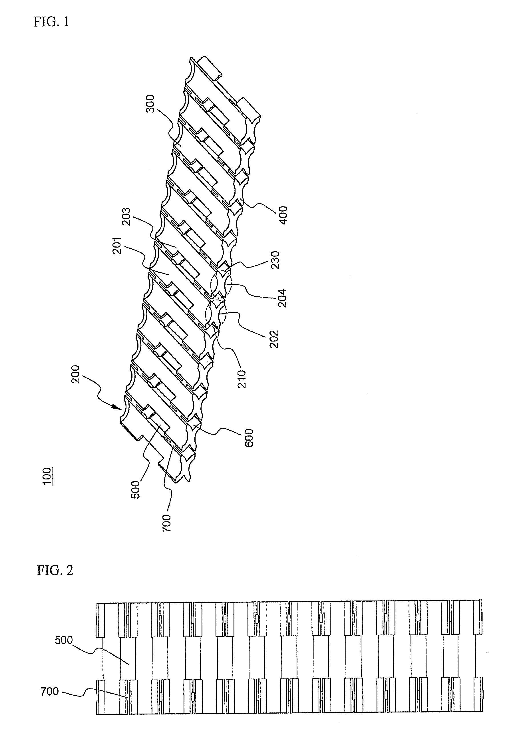
[0037]FIG. 1 is a perspective view illustrating a spacer for battery pack production according to a preferred embodiment of the present invention.

[0038] Referring to FIG. 1, a spacer for battery pack production 100 is constructed in the form of a rectangular frame. The spacer 100 is provided at opposite side surfaces thereof with battery receiving parts 201, 202, 203, and 204, which are formed in a circumferential structure corresponding to the outer surface of each cylindrical unit cell such that a plurality of cylindrical unit cells (not shown) can be received in the respective battery receiving parts 201, 202, 203, and 204. Here, the inner circumference of the battery receiving parts 201, 202, 203, and 204 has a size sufficient to part...


PUM


Abstract

Disclosed herein is a spacer for production of a battery pack using cylindrical batteries as unit cells, wherein the spacer is constructed in the form of a rectangular frame, the spacer is provided at opposite side surfaces (opposite faces) of the rectangular frame with a plurality of battery receiving parts having a circumference-type inner surface structure that partially covers the outer surfaces of the cylindrical batteries, each battery receiving part has a horizontal through-hole, which extends between the opposite side surfaces of the frame, and a pair of battery receiving parts (a unit receiving part) formed at the opposite side surfaces of the frame is connected with another adjacent unit receiving part via structures that can be easily cut. Consequently, the spacer according to the present invention has the effect of allowing the production of a structurally stable battery pack using the minimized number of parts, reducing the number of processes, thereby lowering the costs of products, and preventing the occurrence of short circuits between unit cells during the assembly or the use of the battery pack. In addition, the spacer according to the present invention can be cut into various appropriate sizes, as occasion demands. Consequently, the spacer according to. the present invention has the effect of easily adjusting the capacity and output of a battery pack and effectively removing heat generated from unit cells during the charge and discharge of the unit cells.

Description

FIELD OF THE INVENTION [0001] The present invention relates to a spacer for battery pack production, and, more particularly, to a spacer for production of a battery pack using cylindrical batteries as unit cells, wherein the spacer is constructed in the form of a rectangular frame, the spacer is provided at opposite side surfaces (opposite faces) of the rectangular frame with a plurality of battery receiving parts having a circumference-type inner surface structure that partially covers the outer surfaces of the cylindrical batteries, each battery receiving part has a horizontal through-hole, which extends between the opposite side surfaces of the frame, and a pair of battery receiving parts (a unit receiving part) formed at the opposite side surfaces of the frame is connected with another adjacent unit receiving part via structures that can be easily cut. BACKGROUND OF THE INVENTION [0002] As mobile devices have been increasingly developed, and the demand of such mobile devices has...

Claims


Application Information

Patent Timeline
IPC IPC(8): H01M2/10
CPCH01M2/105Y02E60/10H01M50/213H01M50/20H01M10/052H01M10/613H01M2220/20H01M2220/30
Inventor KANG, DONGHASHIN, JOONYOUNG
Owner LG ENERGY SOLUTION LTD
Why Eureka
Try Eureka