

Stent pattern for high stent retention
a stent pattern and high stent technology, applied in the field of intravascular stents, to achieve the effect of high stent retention, increased stent retention, and high flexibility
- Summary
- Abstract
- Description
- Claims
- Application Information
AI Technical Summary
Benefits of technology
Problems solved by technology
Method used
Image

Examples
Embodiment Construction
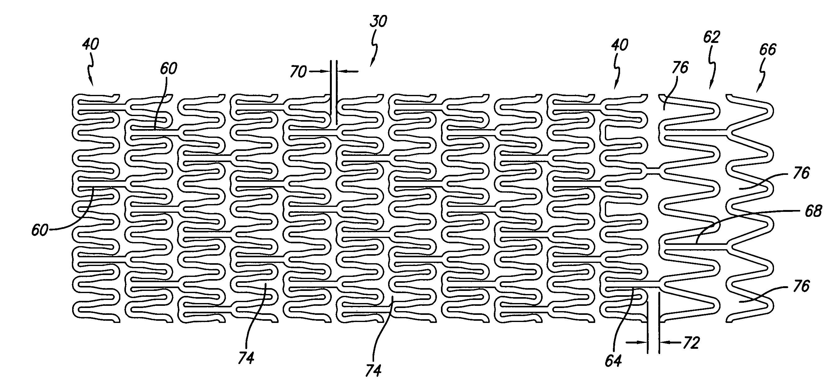
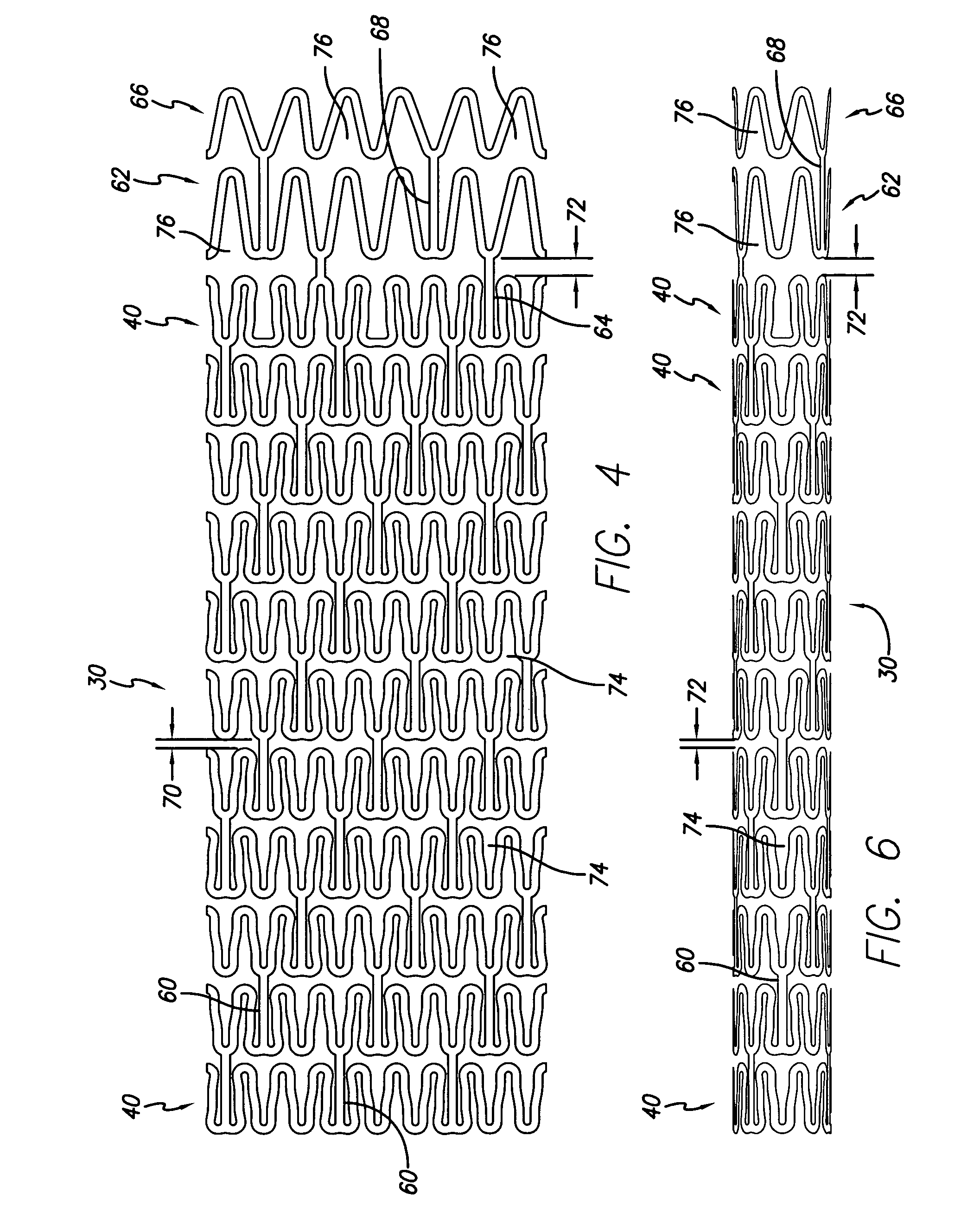
[0028] The present invention stent improves on existing stents by providing a stent pattern that greatly increases the retention force between the stent and the balloon on which it is mounted. The design of highly flexible interconnecting members and their placement relative to cylindrical rings provides for a tightly compressed stent onto a catheter thereby maintaining a high degree of stent retention on the balloon during delivery of the stent to a vessel or duct for implantation.
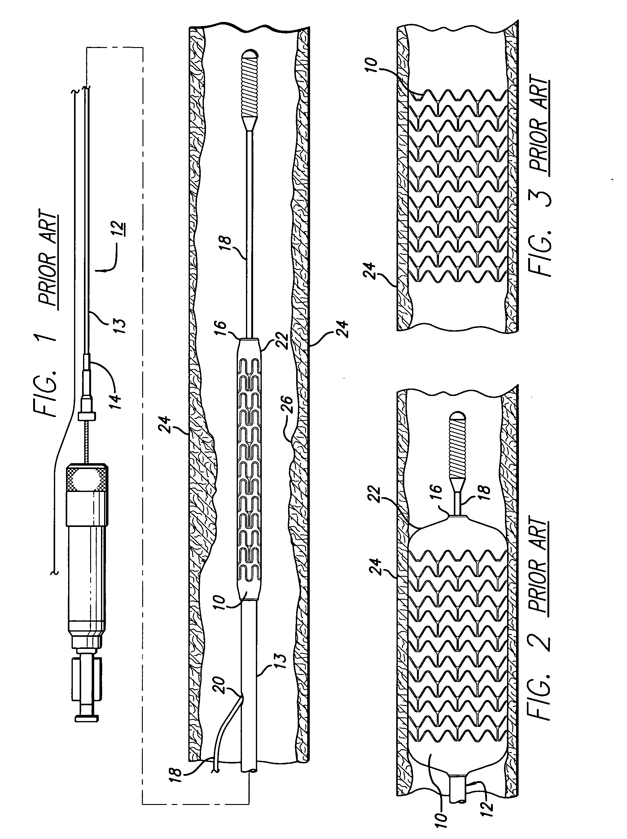
[0029] Turning to the drawings, FIG. 1 depicts a prior art stent 10 mounted on a conventional catheter assembly 12 which is used to deliver the stent and implant it in a body lumen, such as a coronary artery, peripheral artery, or other vessel or lumen within the body. The catheter assembly includes a catheter shaft 13 which has a proximal end 14 and a distal end 16. The catheter assembly is configured to advance through the patient's vascular system by advancing over a guide wire by any of the well know...
PUM
 Abstract
Description
Claims
Application Information