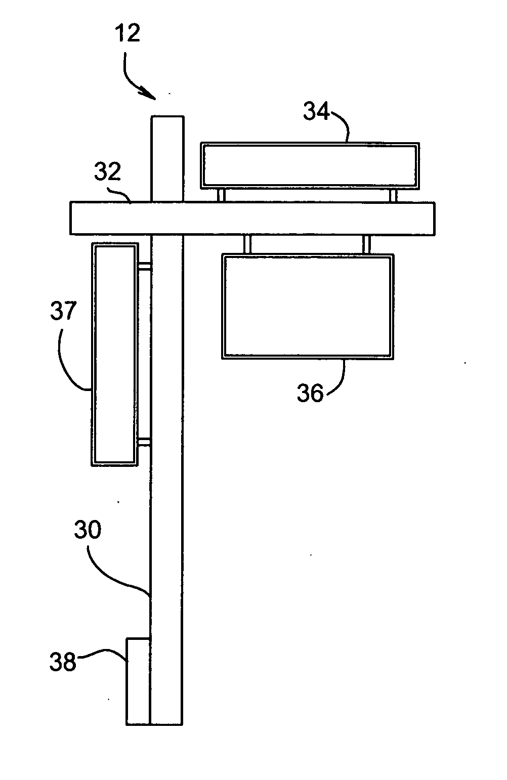
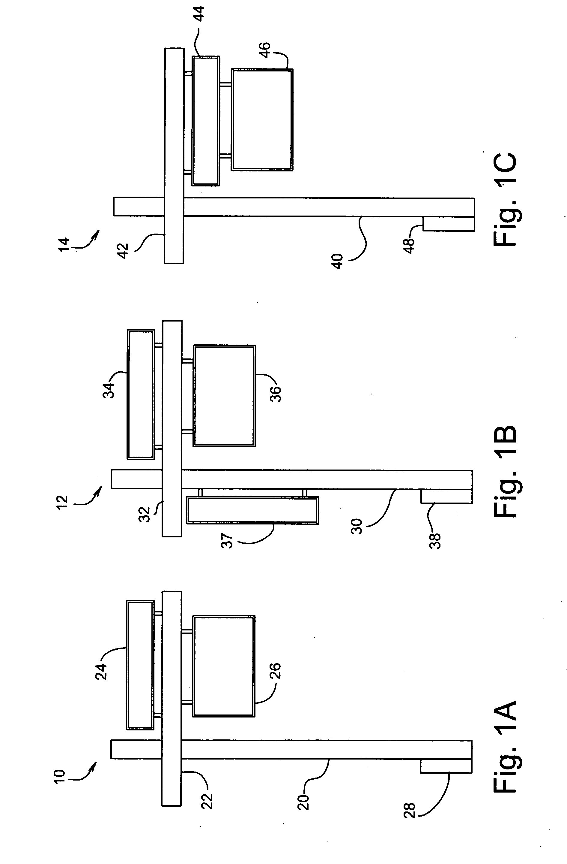
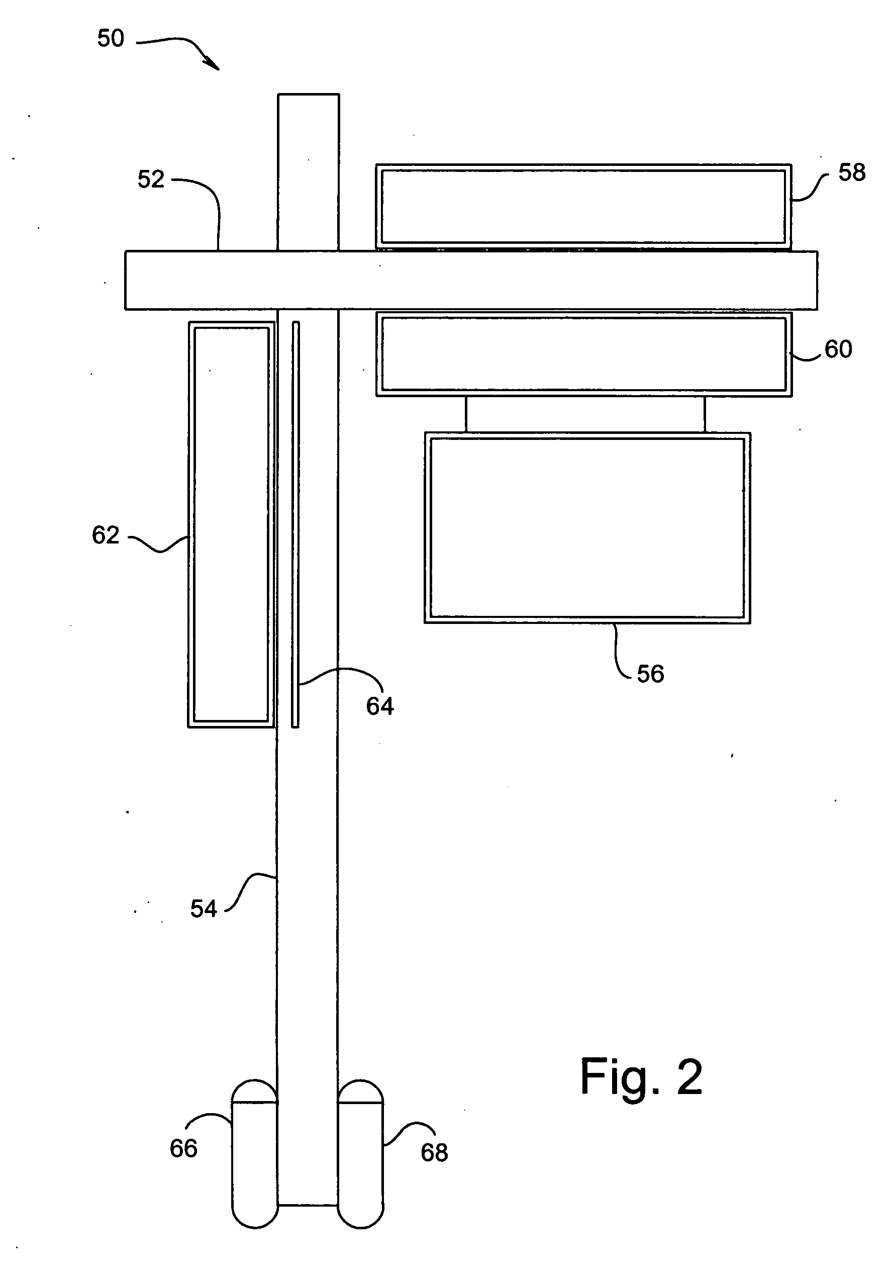
Electric sign with flat light source

Inactive Publication Date: 2007-08-23
LYNN TERRY L +1
View PDF12 Cites 20 Cited by
  • Summary
  • Abstract
  • Description
  • Claims
  • Application Information

AI Technical Summary

Benefits of technology

[0006] The present invention provides an improved electric sign with flat light source arrangement which requires virtually no added expense in producing an illuminated sign in a remote location. The battery operated lighting will provide for the illumination of

Problems solved by technology

Although many lighting systems have been devised in the past, very few have remote site operation capability.
This type of sign is not only expensive to operate, unusable in remote locations but is often seen as a generator of light pollution.
Very ofte

Method used


Image

  • Electric sign with flat light source
  • Electric sign with flat light source
  • Electric sign with flat light source

Examples


second embodiment

[0047]FIG. 13 is a double slide mount sign 220. The internal slotted slide inserts 222 and 224 are protected by frame outer covering 226 and the end caps 228 and 229.

third embodiment

[0048]FIG. 14 is a double slide mount sign in accordance with the present invention with internal slotted slide inserts 232 and 234. A frame outer covering 236 and end caps 238 and 239 protect the sign from the elements. Slots 240, 242, 244, and 246 may accommodate signage.

[0049]FIG. 15 is an embodiment of a single insert slide mount sign 250 with an internal slotted frame 252 and an outer main frame. Slots 256 and 258 are available to accommodate signage.

[0050]FIG. 16 illustrates an alternate embodiment of a sign frame 260 including upper and lower frame members, as depicted by frame member 262. The frame members are held together by two end caps, as depicted by end cap 264. Each frame member 262 includes a threaded well 266 and slots 268 and 272. The flat light source sign (not shown) is slid into one or both slots 268 and 272, before the end caps are fastened into place using upper screw 274 and lower screw 276. Rail guides, as illustrated by rail guide 278 and rail guide 282, l...


PUM


Abstract

An electrically powered sign is provided having a flat transparent sign display panel containing an alphanumeric sign message, a flat light source placed in close proximity, or directly affixed, to the sign display panel, a frame of varying configurations supporting the flat light source and the sign display such that the flat light source, when powered on, shines light through the sign display making the sign message visible in low light conditions, and a serviceable portable power source to provide electrical power to the flat light source, attached to the frame, whereby the electrically powered sign is self-contained and portable, and capable of being placed anywhere for displaying the sign displays alphanumeric sign message.

Description

FIELD OF THE INVENTION [0001] The present invention relates generally to electric signs with flat light sources, and more particularly to a sign incorporating a flat light source as a backlight, thereby providing a sign readable at night or in low light conditions which is controllable and energy efficient. BACKGROUND OF THE INVENTION [0002] Although many lighting systems have been devised in the past, very few have remote site operation capability. One of these systems incorporates a flood light illuminating a sign by emitting a high voltage light from a point in front of the sign. This type of sign is not only expensive to operate, unusable in remote locations but is often seen as a generator of light pollution. [0003] Plastic signage incorporating a light source behind the translucent portion of the sign have been designed, however, again the design requires the attachment of a separate source of electricity. Very often, this light is fluorescent or high voltage incandescent and ...

Claims


Application Information

Patent Timeline
IPC IPC(8): G09F13/22
CPCG09F13/22
Inventor LEMBERGER, ROBERT L.LYNN, TERRY S.HUNT, ROBBIN J.
Owner LYNN TERRY L
Why Eureka
Try Eureka