Apparatus for generating remote plasma

Inactive Publication Date: 2007-08-23
IUCF HYU (IND UNIV COOP FOUNDATION HANYANG UNIV)
View PDF12 Cites 214 Cited by
  • Summary
  • Abstract
  • Description
  • Claims
  • Application Information

AI Technical Summary

Benefits of technology

[0008]An object of the present invention is to provide an apparatus for generating remote plasma th

Problems solved by technology

However, according to the above constitution, the generated plasma does not uniformly react with the substrate mounted in the chamber so that it is difficult to form a thin film uniformly.
Mor

Method used


Image

  • Apparatus for generating remote plasma
  • Apparatus for generating remote plasma
  • Apparatus for generating remote plasma

Examples


Embodiment Construction

[0023]Now, preferred embodiments of the present invention will be described in detail with reference to the accompanying drawings.

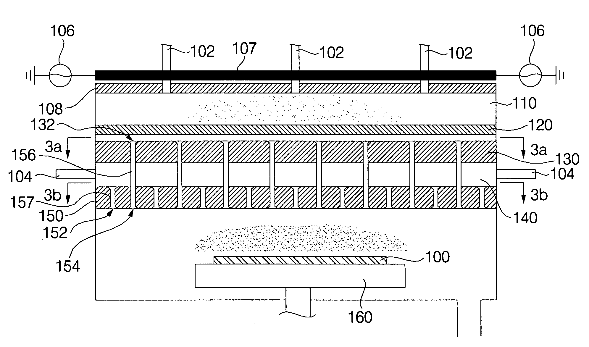
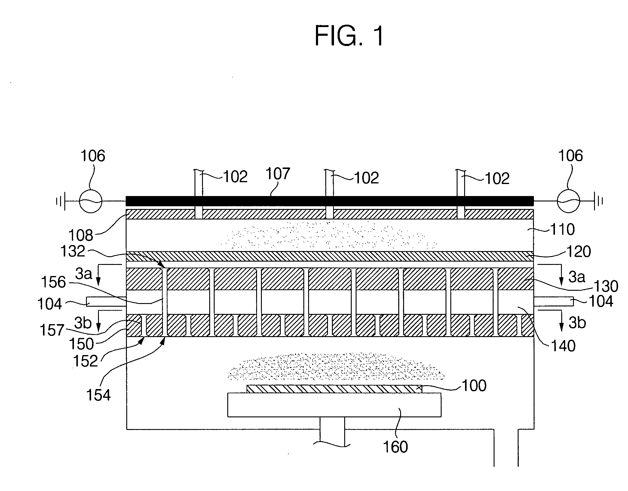
[0024]FIG. 1 is a sectional view of an apparatus for generating remote plasma according to one embodiment of the present invention;

[0025]An apparatus for generating remote plasma includes a radio frequency (RF) antenna, a plasma generating unit 120, a first shower head 130, a source / purge gas introduction unit 140, and a second shower head 150.

[0026]The RF antenna 107 is disposed over an insulating member 108 such as quartz of a chamber, and plays a role in generating plasma. The RF antenna 107 may be configured such that plasma can be uniformly generated.

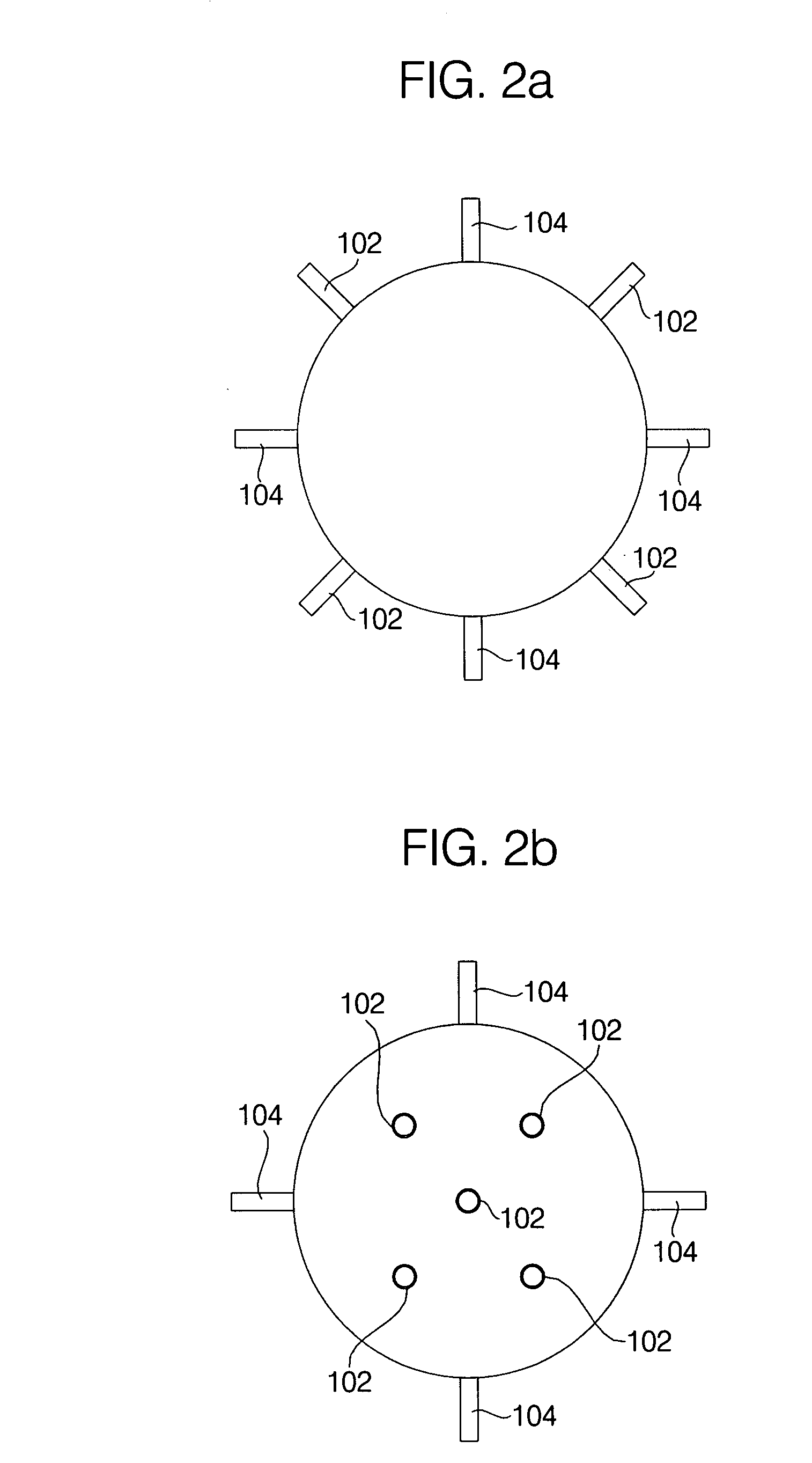
[0027]Specifically, referring to FIG. 6, at least two loop-type antenna elements 10 and 20 are horizontally spaced apart from each other by a predetermined distance such that they are overlapped with each other. The two loop-type antenna elements 10 and 20 are electrically connected in parallel. Herein, ...


PUM

PropertyMeasurementUnit
Diameteraaaaaaaaaa
Distanceaaaaaaaaaa

Abstract

Provided is an apparatus for generating remote plasma. The apparatus includes an RF antenna disposed in regard to a chamber, a plasma generating unit formed in an uppermost portion of the chamber, wherein a plurality of plasma generation gas introduction pipes are communicated with the plasma generating unit, a first shower head disposed below the plasma generating unit, and having a plurality of first plasma guide holes, a second shower head disposed below the first shower head, and having a plurality of source/purge gas guide holes and a plurality of second plasma guide holes directly connected to the respective first plasma guide holes, and a source/purge gas introduction unit disposed between the first and second shower heads, wherein a plurality of source/purge gas introduction pipes are uniformly communicated with the source/purge gas introduction unit.

Description


Claims


Application Information

Patent Timeline
Owner IUCF HYU (IND UNIV COOP FOUNDATION HANYANG UNIV)
Why Eureka
Try Eureka