Gas Supply Facility Of A Chamber And A Fethod For An Internal Pressure Control Of The Chamber For Which The Facility Is Employed

a technology of gas supply facility and internal pressure control, which is applied in the direction of water supply installation, process and machine control, instruments, etc., can solve the problems of difficult to meet the needs of this type of fluid supply facility, unpopularity, and inaccurate flow rate control, and achieves the effect of reducing the facility cost of an exhaust system of a chamber, easy adjustment and maintenance, and accurate flow rate control

Active Publication Date: 2007-08-23
FUJIKIN INC +1
View PDF9 Cites 11 Cited by
  • Summary
  • Abstract
  • Description
  • Claims
  • Application Information

AI Technical Summary

Benefits of technology

[0024] With a gas supply facility to a chamber according to the present invention, the required flow rate range is divided into a plural number of flow rate ranges, and a small flow quantity range of less than 10% of the maximum flow rate is controlled by a pressure type flow controller for a small flow quantity, thus accurate flow rate control being achieved over the wide flow range.
[0025] In addition, it is so constituted that when a flow rate control by pressure type flow controllers allotted to all the flow rate ranges overlaps, the rising rate of control signals is restricted to make the flow rate Q of the gas to be supplied to a chamber continuously controlled.
[0026] With regard to a method for an internal pressure control of a chamber, an internal pressure of a chamber can be easily adjusted to and maintained at a specified set pressure due to the reason that a gas flow rate to be supplied to a chamber can be adjusted accurately and quickly. Accordingly, a conventional
[0027] automatic pressure controller APC can be eliminated, thus making it possible that facility costs for an exhaust system of a chamber are substantially reduced.
[0028] Furthermore, for a vacuum pump, an exhaust volume of the pump needs only to be big enough for the lowest pressure to a chamber previously set,
[0029] not requiring a vacuum pump to have a considerable margin for the exhaust volume as happened with a conventional exhaust system to a chamber. As a result, substantial reduction of the costs for an evacuation system can be achieved.

Problems solved by technology

A combination of a primary vacuum pump (a high vacuum pump) VP1 such as a turbo molecular pump and the like and a secondly vacuum pump (a low vacuum pump) VP2 such as a scroll pump and the like is widely employed for the aforementioned vacuum pump while an exhaust system for which one pump having a large exhaust volume and a large compression ratio is used has a disadvantage in manufacturing costs and the like, so it is not popular.
However, there are found various difficulties with this type of fluids supply facilities.
As a result, an accurate flow rate control cannot be expected in a small flow quantity range of less than 100 SCCM.
Accordingly, equipment costs of a vacuum chamber E go high, and the reduction of the costs becomes difficult to be achieved.

Method used


Image

  • Gas Supply Facility Of A Chamber And A Fethod For An Internal Pressure Control Of The Chamber For Which The Facility Is Employed
  • Gas Supply Facility Of A Chamber And A Fethod For An Internal Pressure Control Of The Chamber For Which The Facility Is Employed
  • Gas Supply Facility Of A Chamber And A Fethod For An Internal Pressure Control Of The Chamber For Which The Facility Is Employed

Examples


first embodiment

The First Embodiment

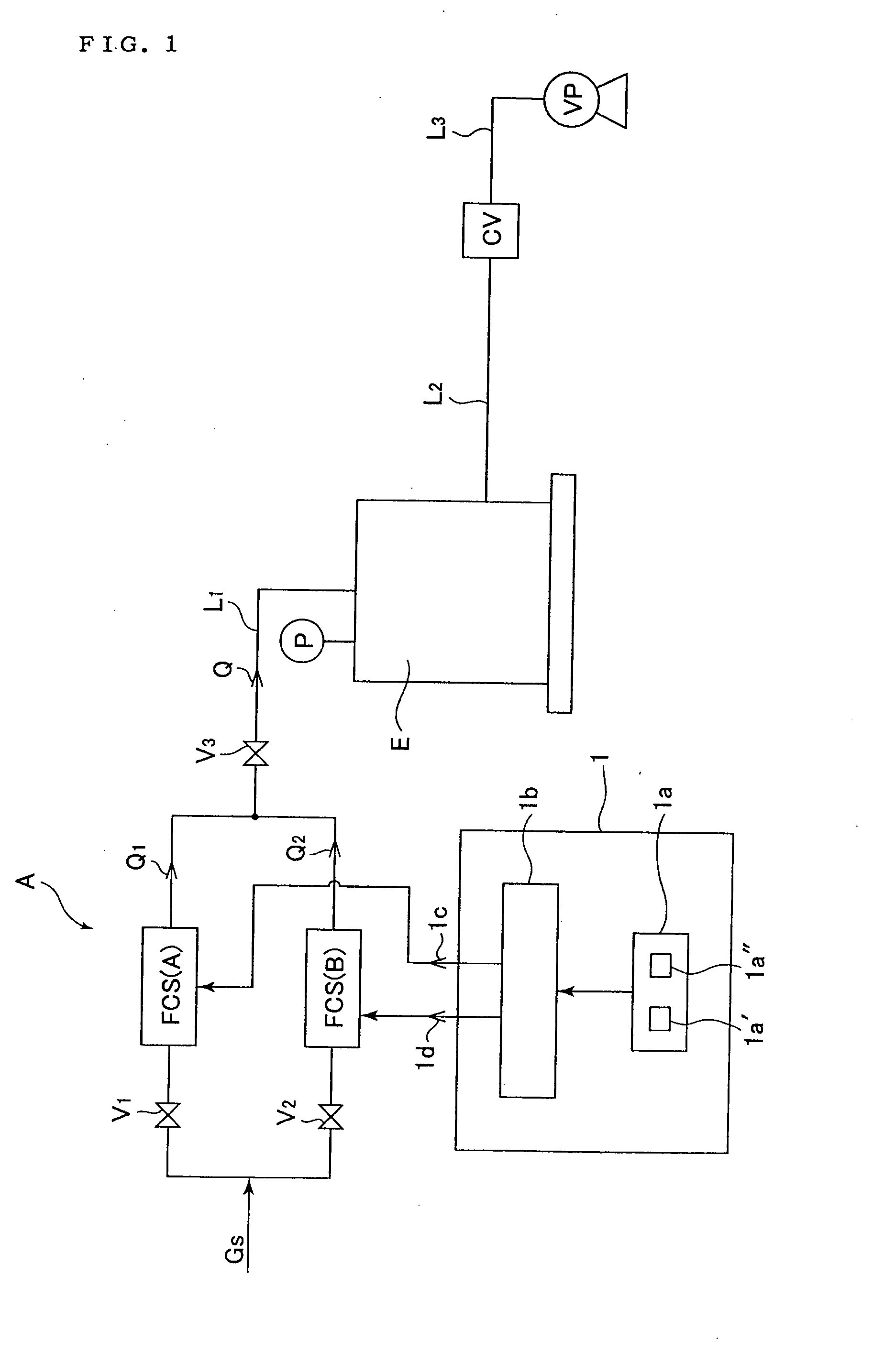
[0063]FIG. 1 shows the first embodiment of a gas supply facility to a chamber according to the present invention, which is a basic pattern of the said

[0064] gas supply facility.

[0065] With FIG. 1, A designates a gas supply facility, Gs a supply gas, FCS(A) a pressure type flow controller for a small flow quantity, FCS(B) a pressure type flow controller for a large flow quantity, E a chamber, Q1 a control flow rate of a pressure type flow controller FCS(A) for a small flow quantity, Q2 a control flow rate of a pressure type flow controller FCS(B) for a large flow quantity, Q a supply flow rate to a chamber E, P pressure inside a chamber E, CV a conductance valve, VP a vacuum pump, V1-V3 control valves, L1 a gas supply pipe, L2 and L3 exhaust pipes, 1 a controller, 1a a flow rate input setting part, 1b a signal conversion part, and 1c and 1d control signals.

[0066] The aforementioned pressure type flow controllers FCS(A) and FCS(B) are basically identical to a co...

second embodiment

The Second Embodiment

[0086]FIG. 5 is a diagram to show relationships between a set flow rate and a flow rate output in the second embodiment for a fluids supply facility according to the present invention. With the said second embodiment, it is so constituted that these pressure type flow controllers FCS(A), FCS(B) and FCS(C) with the rated flow rates of 100 SCCM, 3000 SCCM and 5000 SCCM respectively are employed, thus achieving accurate flow control over the wide flow rate range of 5 SCCM-8100 SCCM.

[0087] With FIG. 5, flow rate characteristics of pressure type flow controllers FCS(A), FCS(B) and FCS(C) are shown by a curve L for 100 SCCM, a curve H for 3000 SCCM and a curve M for 5000 SCCM respectively. Q is a supply flow rate to a chamber E.

[0088] That is, when a supply flow rate Q is less than 100-3100 SCCM, a flow rate Q is determined by a formula:

Q=(3100−10) / (40−1)·(SET %−1)+100

[0089] When a supply flow rate Q is 3100-8100 SCCM, a flow rate Q is determined by a formula:

Q=(...

third embodiment

The Third Embodiment

[0093]FIG. 6 is a whole system diagram to show a method for an internal pressure control of a chamber for which a gas supply facility according to the present invention is employed.

[0094] Referring to FIG. 6, a chamber E has an inside capacity of 11 liters, and its exhaust system comprises a conductance valve CV, a vacuum pump VP, an exhaust pipe L2 and an exhaust pipe L3. A vacuum pump has an exhaust volume of 300 liters / min.

[0095] The method for an internal pressure control of the said chamber is that an internal pressure inside a chamber E continuously exhausted by a vacuum pump having a certain exhaust capacity is regulated to a specified process pressure of approximately 10-10 by finely adjusting the flow rate of fluids supplied therein.

[0096] Referring to FIG. 6, firstly a conductance valve CV is fully opened to make a flow passage resistance to a minimum, and a vacuum pump VP is operated to evacuate a chamber to a degree of vacuum to meet the evacuation...


PUM


Abstract

The present invention makes it possible to prevent substantial reduction of flow rate control accuracy in a small flow quantity range, to achieve an accurate flow rate control over the entire range of a flow rate control, and also to allow control of a wide pressure range of a chamber with an accurate flow rate control. Namely, with a gas supply facility having a plurality of pressure type flow controllers connected in parallel and a controller to control operation of pressure type flow controllers to supply a desired gas exhausted by a vacuum pump to a chamber while controlling its flow rate, one pressure type flow controller is made to be a controller to control a gas flow rate range up to 10% of the maximum flow rate to be supplied to a chamber, while the remaining pressure type flow controllers are made to be ones to control the rest of the gas flow rate range.

Description

FIELD OF THE INVENTION [0001] The present invention is concerned with a facility for gas supply to a chamber utilized with semiconductor manufacturing facilities and the like, and a method for an internal pressure control of the chamber for which the facilities is employed. BACKGROUND OF THE INVENTION [0002] In recent years, gas supply facilities equipped with a so-called pressure type flow controller to be used for a gas supply facility to a process chamber have been widely used. [0003] An example is illustrated in FIG. 8. It is so constituted that pressure type flow controllers C1, C2 and C3 and fluids switching valves D1, D2 and D3 are provided with a gas supply facility, and switching of fluids supplied to a process chamber E and flow rate adjustments are automatically performed by signals from a controller B (TOKU-KAI-HEI No. 11-212653 and others). [0004] It is so constituted that, with the aforementioned pressure type flow controllers C1, C2 and C3, a flow quantity Qc passing ...

Claims


Application Information

Patent Timeline
Patent Type & Authority Applications(United States)
IPC IPC(8): G05D7/06H01L21/02
CPCG05D7/0652Y10T137/8741Y10T137/7761Y10T137/87507G05D7/00
Inventor KANNAN, HIROSHIUNO, TOMIODOHI, RYOUSUKENISHINO, KOUJINAKAMURA, OSAMUMATSUMOTO, ATSUSHIIKEDA, NOBUKAZU
Owner FUJIKIN INC
Why Eureka
Try Eureka