Image forming apparatus and electric-power control method

a technology of electric power control and forming apparatus, which is applied in the direction of electrographic process, manufacturing tools, instruments, etc., can solve the problems of excessive electric current and excessive quantity of electric power supplied depending on paper type, and achieve the effect of increasing the burden of electric power control

Active Publication Date: 2007-08-23
CANON KK
View PDF9 Cites 25 Cited by
  • Summary
  • Abstract
  • Description
  • Claims
  • Application Information

AI Technical Summary

Benefits of technology

[0015] As described above, according to the present invention, an electric power supply can be controlled below a maximum suppliable current value by detecting an applied current of the heater without supplying an excessive electric current to the heater that is a constituent element of the fixing ...

Problems solved by technology

Since the sequence controller controls the thermal fixing device so as to keep the thermal fixing device at the predetermined temperature, there is the possibility that an excessive quantity of electric power will be supplied de...

Method used


Image

  • Image forming apparatus and electric-power control method
  • Image forming apparatus and electric-power control method
  • Image forming apparatus and electric-power control method

Examples


first embodiment

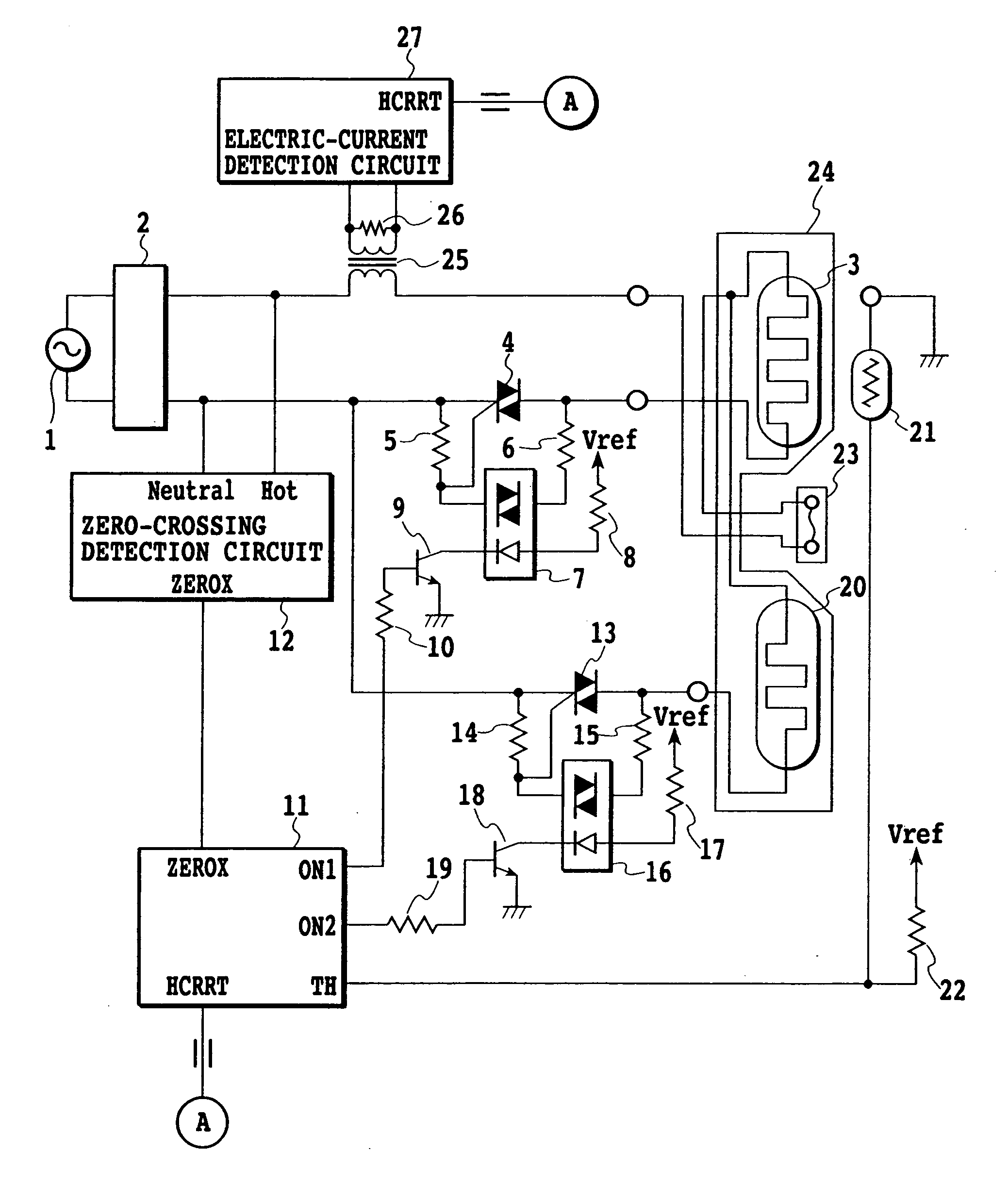
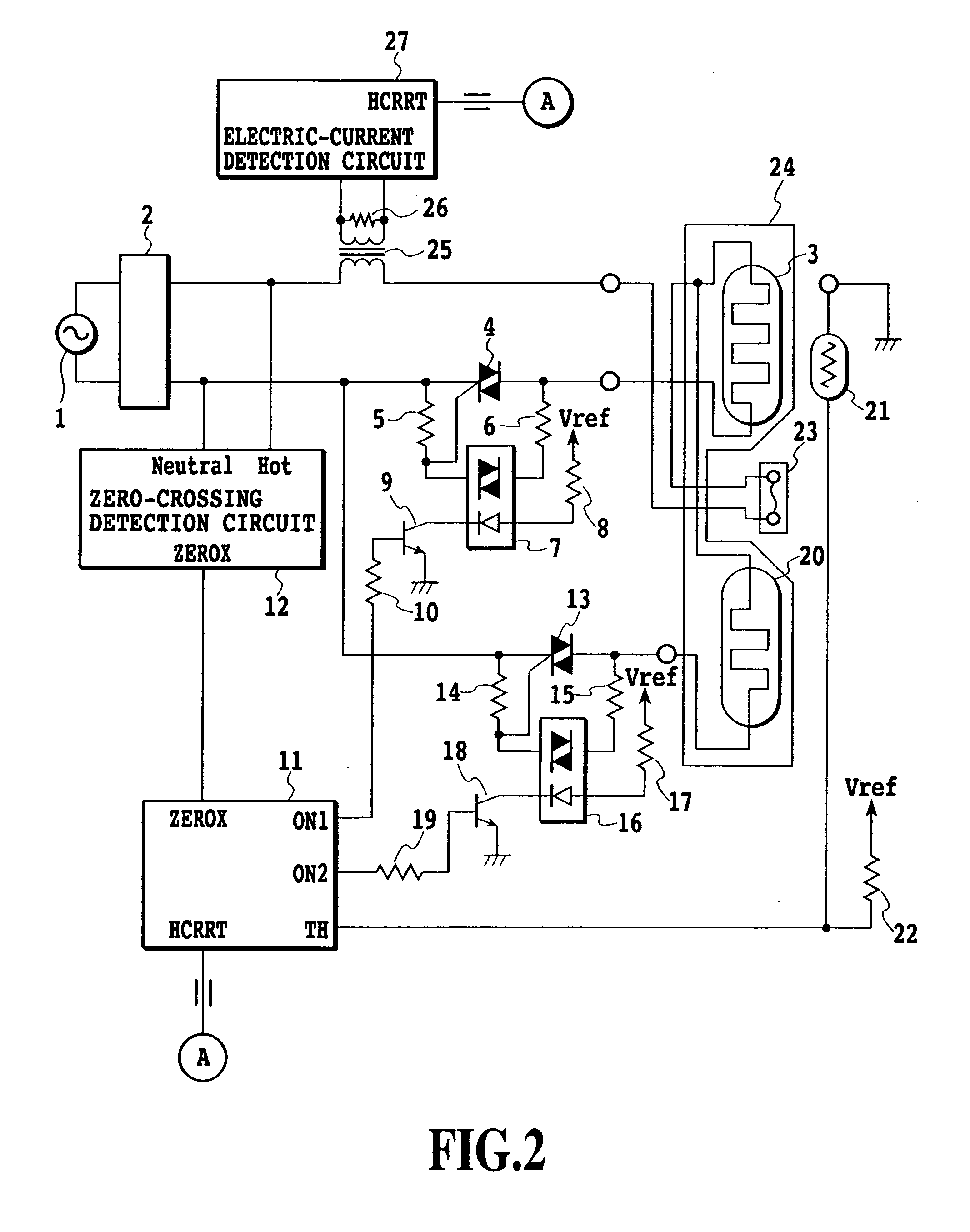
[0048]FIG. 7 shows a control sequence of the fixing device according to the present invention. FIGS. 8A-8E show operation waveforms of a heater current and ON1 and ON2 signals. When the engine controller 11 is required to start supplying electric power to the ceramic heater 24 (S1), an electric current is applied to both of the heating elements 3 and 20 with the same, predetermined fixed duty D1 (S2). The term “duty” denotes the percentage of electric power obtained when a heater current is supplied at an arbitrary phase angle on the supposition that electric power obtained when the full-wave supply of a heater current is carried out is regarded as “100.” The engine controller 11 sends ON1 and ON2 signals, with a ZEROX signal (see FIG. 8C) as a trigger, at a phase angle α1 corresponding to the fixed duty D1 (see FIG. 8B). The heater is supplied with the heater current at the phase angle α1 (see FIG. 8A).

[0049] While the heater current is being applied at the fixed duty D1, a current...

second embodiment

[0054]FIG. 9 shows a control sequence of the fixing device according to the present invention. FIGS. 10A-11E show operation waveforms of a heater current and ON1 and ON2 signals. When the engine controller 11 is required to start supplying electric power to the ceramic heater 24 (S21), an electric current is applied to both of the heating elements 3 and 20 with the same, predetermined fixed duty D1 (S22). The engine controller 11 sends ON1 and ON2 signals, with a ZEROX signal (see FIG. 10C) as a trigger, at a phase angle α1 corresponding to the fixed duty D1. The heater is supplied with the heater current at the phase angle α1.

[0055] While the heater current is being applied at the fixed duty D1, a current value I1 of the heater current is detected in accordance with an HCRRT signal sent from the electric-current detection circuit 27 (S23). The fixed duty D1 is set not to exceed an allowable current in consideration of a presupposed input voltage range and a resistance value of the ...


PUM

PropertyMeasurementUnit
Temperatureaaaaaaaaaa
Currentaaaaaaaaaa

Abstract

An electric power supply is controlled below a maximum suppliable current value by detecting the applied current of a heater. The image forming apparatus includes a heater which includes heating elements that generate heat when electric power is supplied, a current detector for detecting a current value supplied to the heater, a temperature detector for detecting the temperature of the fixing device, and an electric power controller for supplying electric power to the heater with a current application duty based on the temperature detected by the temperature detector within a range below a maximum current application duty. The maximum current application duty can be reset based on a current application duty to the heater and based on a current value detected by the current detector.

Description

[0001] This application claims priority from Japanese Patent Application No. 2003-188738 filed Jun. 30, 2003, which is incorporated hereinto by reference. BACKGROUND OF THE INVENTION [0002] 1. Field of the Invention [0003] This invention relates to an image forming apparatus and an electric-power control method, and more particularly, to an image forming apparatus that uses a ceramic surface heating system as a heating means and to an electric-power control method. [0004] 2. Description of the Related Art [0005] Conventionally, an image forming apparatus that uses an electrophotographic process is known. A thermal fixing device in the image forming apparatus fixes an unfixed image (toner image) formed on transfer paper by an image forming means, such as an electrophotographic process, onto the transfer paper. A device having a roller heating system that uses a halogen heater as a heat source or a device having a film heating system that uses a ceramic surface heater as a heat source...

Claims


Application Information

Patent Timeline
IPC IPC(8): H05B3/00G03G15/20
CPCG03G2215/2016G03G15/2039H05B3/0095G03G2215/2035
Inventor ICHINO, TOSHIYUKI
Owner CANON KK
Why Eureka
Try Eureka