Aircraft wing with electrothermal deicing and/or Anti-icing device

an electrothermal deicing and anti-icing technology, applied in aircraft components, de-icing equipment, transportation and packaging, etc., can solve the problems of long delay, runback refreeze, etc., and achieve the effect of preventing runback refreez

Inactive Publication Date: 2007-08-23
THE BF GOODRICH CO
View PDF9 Cites 21 Cited by
  • Summary
  • Abstract
  • Description
  • Claims
  • Application Information

AI Technical Summary

Benefits of technology

[0009] If the aircraft has a large wing sweep angle (e.g., greater than 300), the electrothermal device can be designed to provide a primary deicing zone which underlies a major percentage of the surface area of the structural member, including the apex of the structural member. An upper deicing “catch” zone can be provided, which is positioned and operated to prevent runback refreeze on unheated upper aft surfaces of the wing. Specifically, as runback (i.e., melted ice) flows in the aft direction from the primary deicing zone, it refreezes in the catch zone and can then be shed therefrom by activation of this secondary deicing zone.

Problems solved by technology

An actuation delay is the time it takes for an automatic ice detector to react to an icing condition and provide an “on” signal.
A long delay (e.g., two minutes) can occur when an automatic ice detection system fails and the pilot does not immediately realize that the aircraft is in an icing condition.
In any event, an actuation delay can result in an ice cap forming between the structural member and the moveable flap portion.
If icing conditions are comparably cold and / or the delay is relatively long, the notch's anti-icing zone may not be able to completely melt the ice cap.

Method used


Image

  • Aircraft wing with electrothermal deicing and/or Anti-icing device
  • Aircraft wing with electrothermal deicing and/or Anti-icing device
  • Aircraft wing with electrothermal deicing and/or Anti-icing device

Examples


Embodiment Construction

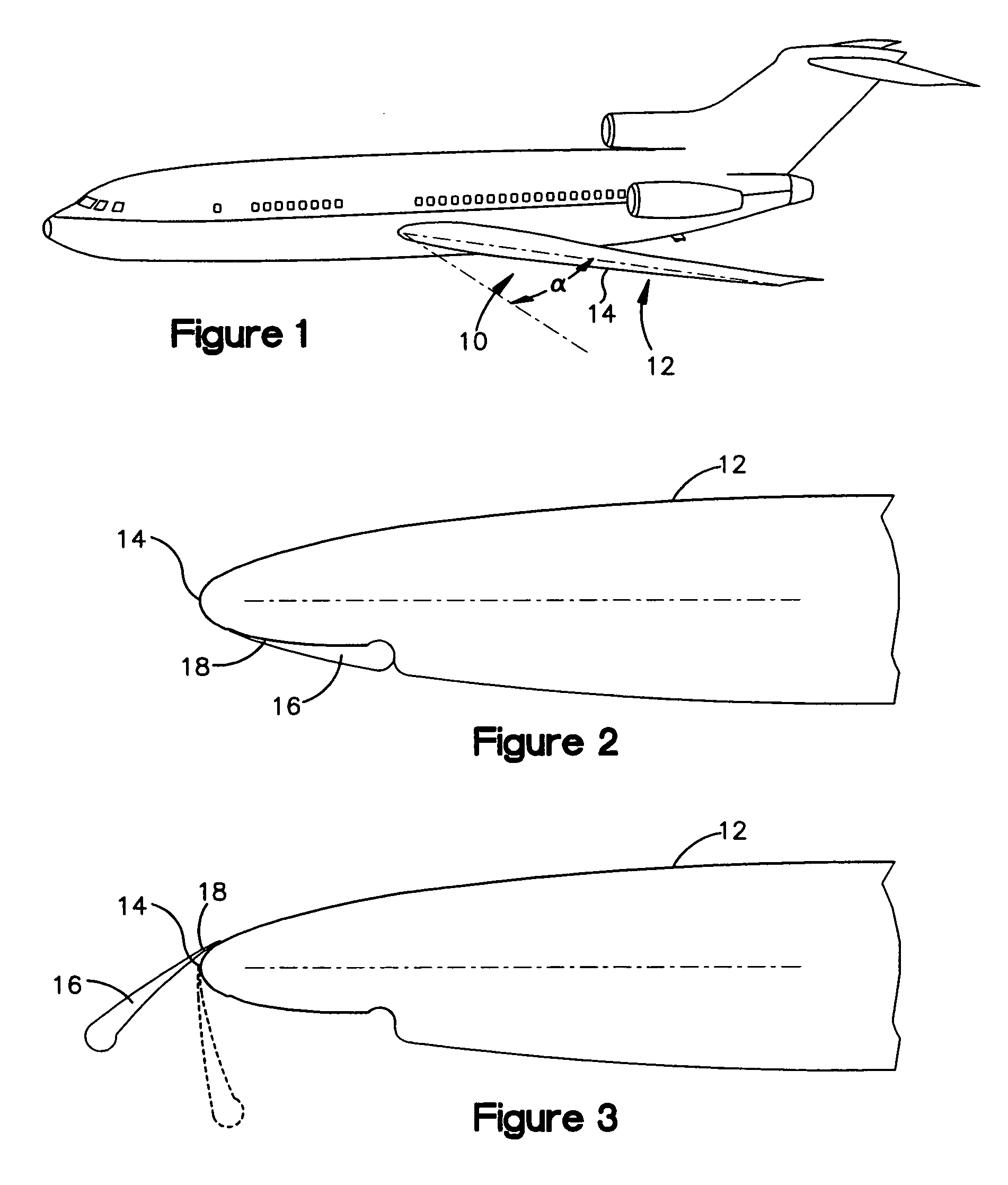
[0018] Referring now to the drawings, and initially to FIG. 1, an aircraft 10 having aircraft wings 12 according to the present invention is shown. In the illustrated embodiment, the aircraft 10 has a sweep angle a which is greater than 300 and, more particularly, about 340. During flight, air passes over the leading edges 14 of the wings 12 in a fore-to-aft to direction.

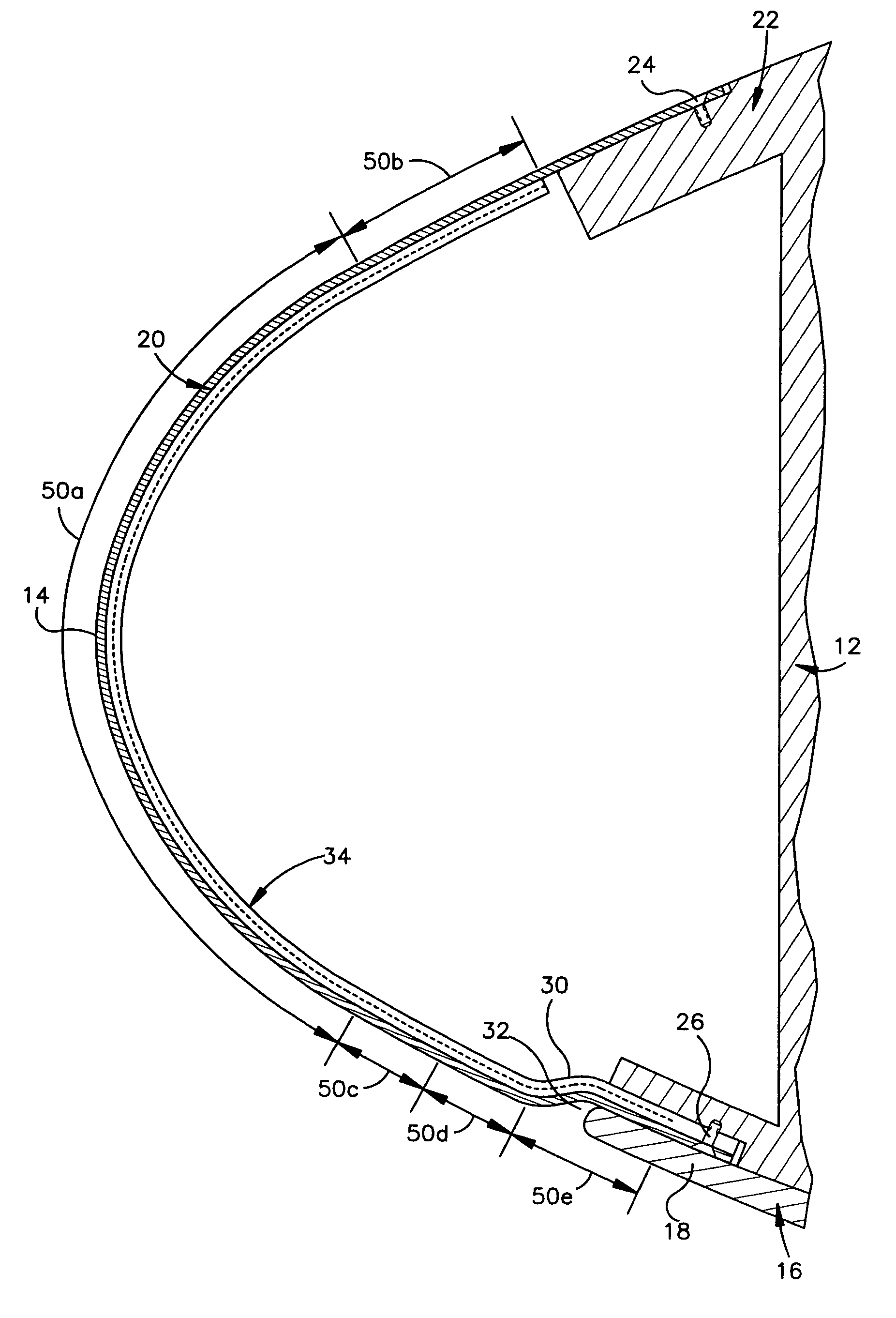
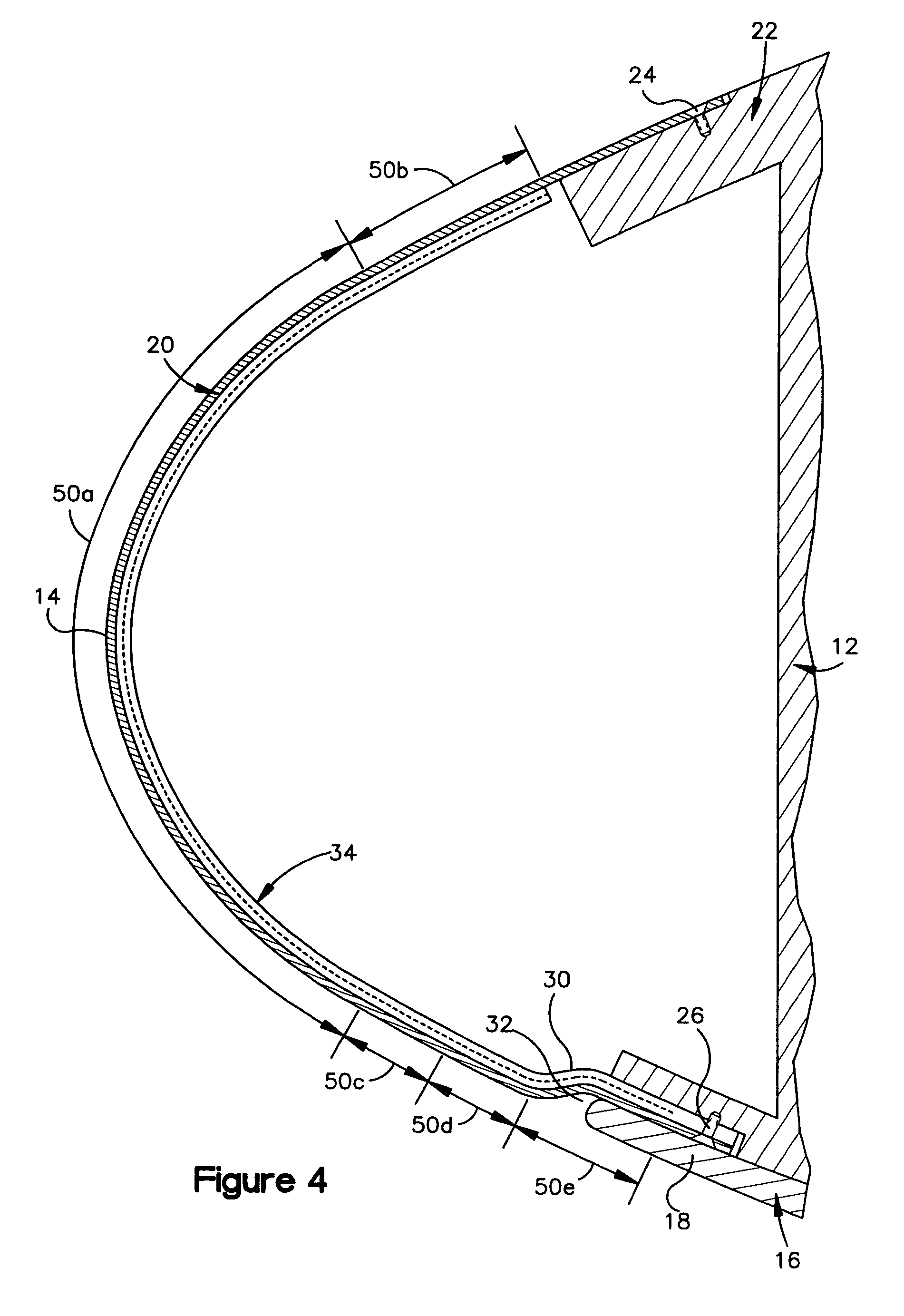
[0019] Referring now to FIGS. 2 and 3, each wing 12 includes a rigid flap 16 which moves between a stowed position and a deployed position. In the stowed position, the flap 16 lies flush with, or forms a portion of, the lower surface of the wing 12. (FIG. 2.) In the deployed position, the flap 16 is pivoted outwardly to form in essence an extension of the convex upper surface of the wing 12. (FIG. 3.) (Flap positions between the illustrated stowed / deployed positions are also possible, as is well known in the art.) The flap 16 can comprise a thin composite construction or any other appropriate material. It is noted ...


PUM


Abstract

An aircraft wing (12) comprising a structural member (20) forming the wing's leading edge skin, a Kreuger flap (16) which moves relative to the structural member (20) between a stowed position and a deployed position, and an electrothermal device (34) mounted (e.g., internally mounted) to the structural member (20). An aft portion (30) of the structural member (20) is curved inwardly to form a recess (32), and a fore portion (18) of the flap (16) fits within the notch (32) to form a joggle therebetween. The electrothermal device (34) is a deicing and/or anti-icing device which continuously provides heat to the curved aft portion (30) of the structural member (20) during icing conditions so as to prevent deployment-inhibiting ice buildup on the flap (16).

Description

RELATED APPLICATION [0001] This application claims priority under 35 U.S.C. §119(e) to U.S. Provisional Patent Application No. 60 / 549,752 filed on Mar. 3, 2004. The entire disclosure of this earlier application is hereby incorporated by reference.FIELD OF THE INVENTION [0002] This invention relates generally, as indicated, to an aircraft wing with an electrothermal deicing / anti-icing device and, more particularly, to an aircraft wing having a leading edge flap and an electrothermal device to insure proper deployment of the flap in icing conditions. BACKGROUND OF THE INVENTION [0003] An aircraft wing is specifically designed to provide the necessary lift to carry the weight of the aircraft at desired speeds and / or altitudes. At high cruising speeds, the required airfoil area is significantly less than that required at slow landing speeds. For this reason, it is common for an aircraft wing to include a leading edge flap (often called a Kreuger flap) which moves between a stowed positi...

Claims


Application Information

Patent Timeline
Patent Type & Authority Applications(United States)
IPC IPC(8): B64D15/12B64C9/24B64D15/14B64D15/20
CPCB64C9/24B64D15/14B64D15/12
Inventor GIAMATI, MICHAEL
Owner THE BF GOODRICH CO
Why Eureka
Try Eureka