Piezoelectric actuator, drive control method of piezoelectric actuator, and electronic device

a technology of piezoelectric actuator and actuator, which is applied in the direction of electric winding, instruments, horology, etc., can solve the problems of difficult drive control, inability to accurately recognize resonance, and difficult efficient drive of actuator, so as to simplify the structure of the drive circuit, facilitate control, and stabilize the effect of the actuator

Inactive Publication Date: 2007-08-23
SEIKO EPSON CORP
View PDF4 Cites 12 Cited by
  • Summary
  • Abstract
  • Description
  • Claims
  • Application Information

AI Technical Summary

Benefits of technology

[0124]According to the above-described exemplary embodiment, following advantages can be obtained.
[0125](1) Since the two-phase drive signals D1 and D2 (+ or −) having a predetermined phase difference are respectively input to the first vibration area R1 and the second vibration area R2 and the vibrating condition of the piezoelectric actuator 20 as a drive member of the date display device 10 is detected by the detection electrode (261 or 262) provided on one of the first vibration area R1 and the second vibration area R2 to which at least the phase-delay drive signal is supplied, the phase difference (detected phase difference) between the vibration signal detected by the detection electrode and the drive signal D1 exhibits monotonic increase, which can be used as a setting parameter for controlling the drive of the actuator. Accordingly, complicated algorithm and large-scale circuit are not required, and the frequency of the drive signals D1 and D2 can be easily controlled. Since the frequency of the drive signals D1 and D2 are controlled, deviation of the resonance on account of temporal change can be corrected, thereby achieving stable drive of the actuator.
[0126]Further, since the frequency of the drive signals D1 and D2 can be defined solely by the detected phase difference between the vibration signal S1 or S2 and the drive signal D1, the structure of the drive circuit can be simplified, thereby achieving cost reduction and improvement in reliability.
[0127](2) In the piezoelectric actuator 20 having normal rotation mode and reverse rotation mode of the rotor 30, since the detection electrodes 261 and 262 are provided on both of the first vibration area R1 and the second vibration area R2 in axisymmetric manner with respect to the bisector L1, irrespective of asymmetric arrangement of strain distribution on account of the presence of the phase difference of the drive signal (drive phase difference), the strain can be similarly detected in both of the normal rotation mode and the reverse rotation mode. Accordingly, the frequency of the drive signal can be controlled based on the detected phase difference, where the drive performance during the normal rotation and reverse rotation can be made substantially equal or differentiated in a predetermined manner.
[0128](3) Since the detection electrode 261 and the detection electrode 262 are disposed along the circumferential direction of the piezoelectric elements 21 and 22, not only the respiratory vibration mode expanding and contracting in radial direction but also eccentric mode on account of the phase difference of the respiratory vibration can be detected by the respective detection electrodes 261 and 262 as passive strain at the portion where the detection electrodes 261 and 262 are provided. Both of the vibration of respiratory vibration and eccentricity can be detected, based on which the frequency of the drive signals D1 and D2 can be properly controlled. Further, since the strain on account of the eccentricity in addition to the strain generated by the respiratory vibration is generated on the portion on which the detection electrodes 261 and 262 are provided, the voltage of the vibration signals S1 and S2 can be set large, so that the vibration can be clearly detected.
[0129](4) Since the width W of the piezoelectric elements 21 and 22 are smaller than the length L, the smaller displacement on account of eccentricity than that of the respiratory vibration can be detected at the portion of the piezoelectric elements 21 and 22 on which the detection electrodes 261 and 262 are provided, so that drive control in accordance with detected phase difference can be properly conducted.

Problems solved by technology

Since the related-art ring-shaped piezoelectric actuator as shown in Document 1 is driven without detecting the vibration generated on the piezoelectric actuator, resonation cannot be accurately recognized and efficient drive of the actuator have been difficult.
In other words, the phase difference of the vibration signal relative to the drive signal is an index for controlling the drive of the actuator, and the drive control becomes difficult if the phase difference is not monotonic increase or decrease because the direction for increasing or decreasing the drive frequency cannot be determined.
Accordingly, since the drive frequency is not appropriately controlled, the piezoelectric actuator may be excessively excited to cause damage on the actuator.
When the drive of the piezoelectric actuator is to be controlled based on the detected phase difference of the vibration signal relative to the drive signal, since the drive signal has a predetermined drive phase difference and the strain distribution of the piezoelectric element is asymmetry with respect to the bisector, it is difficult to determine on which part of the piezoelectric element the detection electrode is to be located.
As described above, since the drive signal has a predetermined drive phase difference and the strain distribution of the piezoelectric element is asymmetric with respect to the bisector, it is difficult to detect the vibrating condition when plus and minus of the drive phase difference is switched if the detection electrode is provided on only one of the first and the second vibration areas.
Since the piezoelectric actuator includes a ring-shaped piezoelectric element, great torque can be obtained and thick pointer and date dial can be driven, which enhances stateliness and expensive-looking of the timepiece.

Method used


Image

  • Piezoelectric actuator, drive control method of piezoelectric actuator, and electronic device
  • Piezoelectric actuator, drive control method of piezoelectric actuator, and electronic device
  • Piezoelectric actuator, drive control method of piezoelectric actuator, and electronic device

Examples


Embodiment Construction

)

[0053]An exemplary embodiment of the invention will be described below with reference to the attached drawings.

[0054]Incidentally, the same reference numeral will be attached to the same components as those described above, whereby description thereof will be simplified or omitted.

1 Entire Arrangement

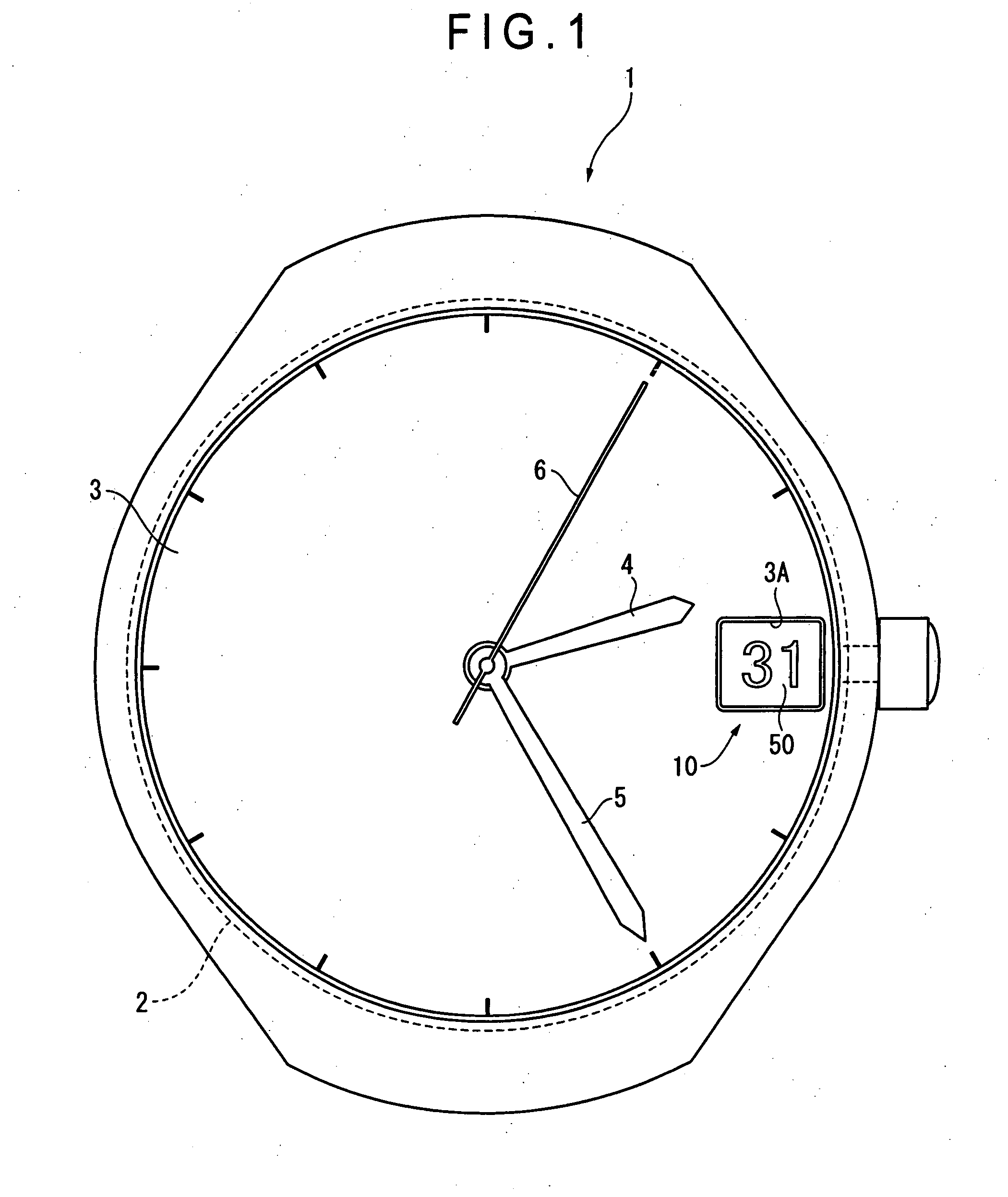
[0055]FIG. 1 shows an exterior of an electronic timepiece 1 according to an exemplary embodiment. The electronic timepiece 1 is a wristwatch including a movement 2 (clock), a time information display for displaying time which includes dial plate 3, hour hand 4, minute hand 5 and second hand 6, and a date display device 10 for displaying date through a window 3A provided on the dial plate 3.

2 Arrangement of Date Display Device

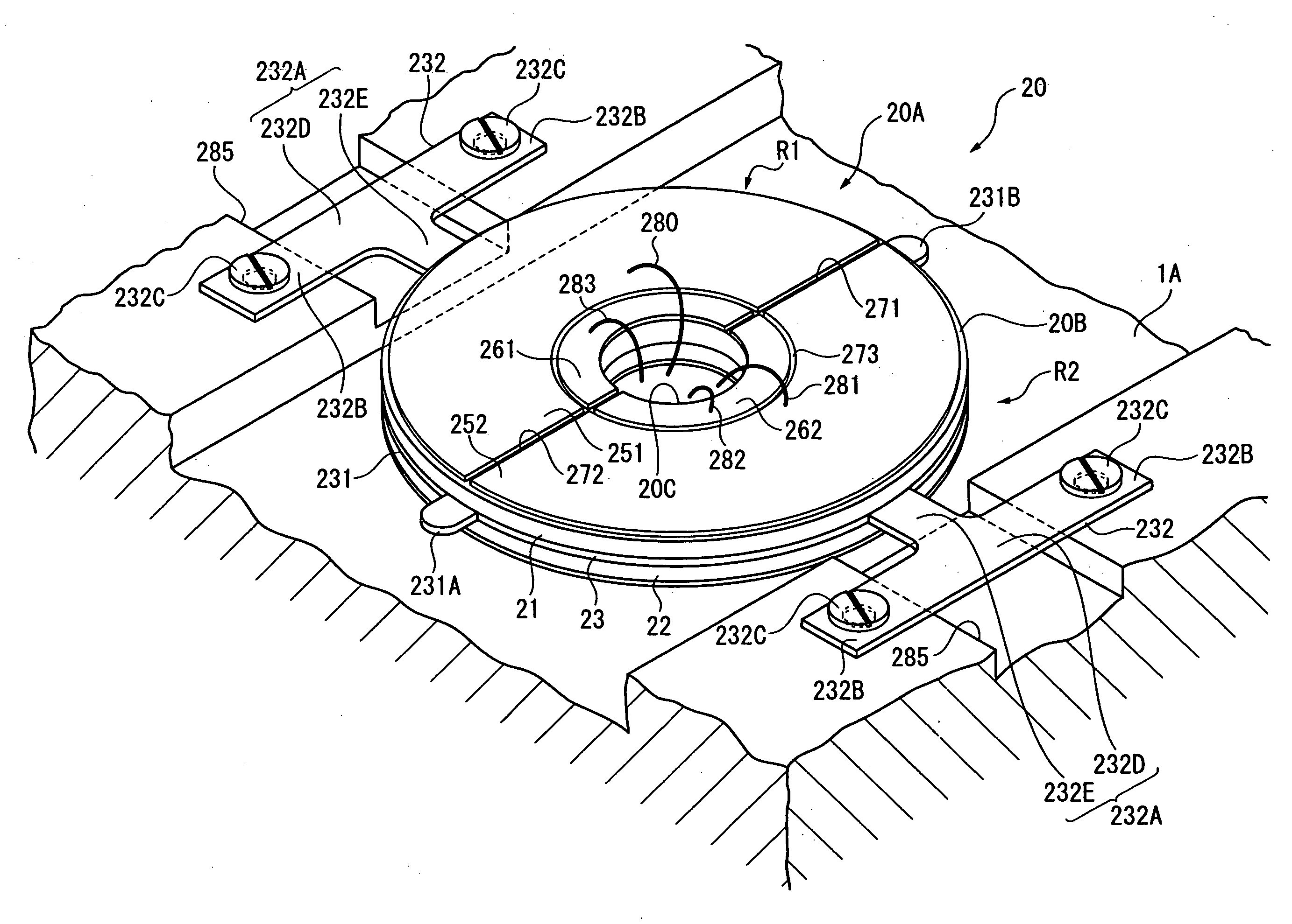
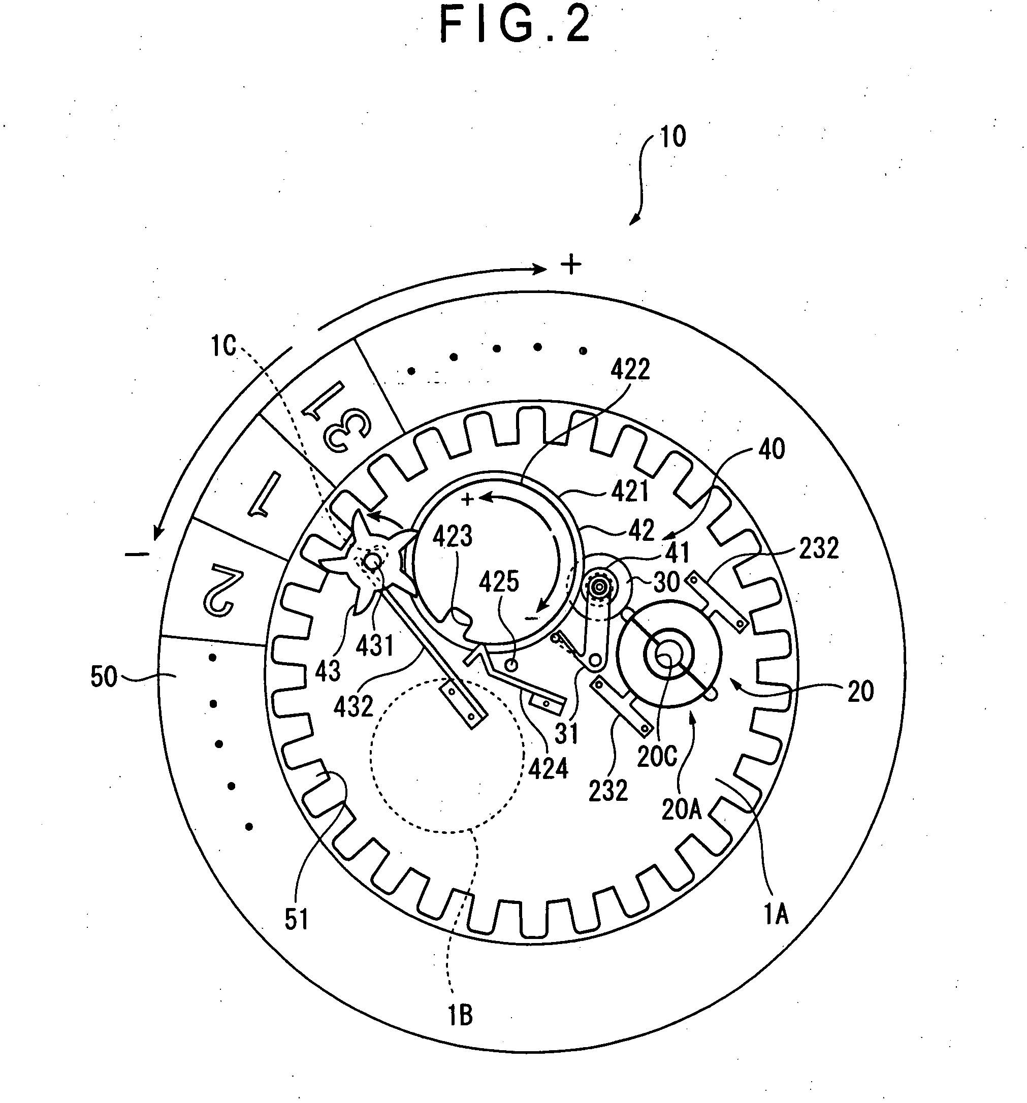
[0056]FIG. 2 is a plan view showing a date display device 10 supported by a bottom plate 1A. The date display device 10 includes a piezoelectric actuator 20, a rotor 30 (object to be driven) rotated by the piezoelectric actuator 20, a deceleration gear train 40 for...


PUM


Abstract

A piezoelectric actuator includes: a ring-shaped piezoelectric element, vibration of the piezoelectric element being transmitted to an object; a first vibration area and a second vibration area provided on both sides of a bisector bisecting the piezoelectric element along a diameter of the piezoelectric element, the first vibration area and the second vibration area being respectively provided with at least one drive electrode to which a drive signal is supplied, the drive electrode being arranged substantially axisymmetrically with respect to the bisector, the drive signal including a phase-advance drive signal and a phase-delay drive signal having a predetermined drive phase difference, the phase-advance drive signal that is phase-advanced relative to the phase-delay drive signal being supplied to one of the first vibration area and the second vibration area and the phase-delay drive signal that is phase-delayed relative to the phase-advance drive signal being supplied to the other of the first vibration area and the second vibration area; and a detection electrode that detects vibrating condition of the piezoelectric element to output a vibration signal, the detection electrode being provided on at least one of the first vibration area and the second vibration area to which the phase-delay drive signal is supplied, the drive of the piezoelectric actuator being controlled based on a detected phase difference between one of the phase-advance drive signal and the phase-delay drive signal and the vibration signal.

Description

[0001]The entire disclosure of Japanese Patent Application No. 2006-40210, filed Feb. 17, 2006, is expressly incorporated by reference herein.BACKGROUND[0002]1. Technical Field[0003]The invention relates to a piezoelectric actuator, a drive control method of piezoelectric actuator, and an electronic device[0004]2. Related Art[0005]In view of excellent conversion efficiency from electric energy to mechanical energy and high responsivity of piezoelectric element, a piezoelectric actuator that drives an object by transmitting a vibration of a piezoelectric element has been recently developed.[0006]One of known piezoelectric actuators employs a ring piezoelectric element (Document 1: Japanese Patent Laid-Open Publication No. 2005-86884). Since such piezoelectric actuator has greater electromechanical coupling coefficient of piezoelectric element than a piezoelectric element of a shape having longitudinal direction (e.g. rectangle), large output can be obtained for the dimension thereof....

Claims


Application Information

Patent Timeline
Patent Type & Authority Applications(United States)
IPC IPC(8): H01L41/08
CPCG04C3/12G04C17/0058H02N2/142H02N2/103H02N2/123H02N2/002H02N2/0035
Inventor HASHIMOTO, YASUHARU
Owner SEIKO EPSON CORP
Why Eureka
Try Eureka