Filter and coil connecting frame thereof

a filter and coil technology, applied in the direction of inductance, printed circuit aspects, coupling device connections, etc., can solve the problems of increasing the number of coils which require soldering, time-consuming, and increasing the number of coils, so as to simplify manual labor procedures, improve the yield and good rate of finished products, and achieve high-quality soldering

Inactive Publication Date: 2007-08-23
DELTA ELECTRONICS INC
View PDF7 Cites 21 Cited by
  • Summary
  • Abstract
  • Description
  • Claims
  • Application Information

AI Technical Summary

Benefits of technology

[0016]Accordingly, the coil connecting frame forms a unitary filter monomer. The number of unitary monomers is determined by filter design requirements. When one of the unitary monomers failures, only the broken monomer needs to be exchanged for a new one but the entire filter does not require exchange. Moreover, the unitary monomer can be tested during the manufacturing process so that the yield and good rate of the finished products can be increased.
[0017]Compared with a conventional method of manufacturing a coil, the coil connecting frame of the invention includes grooves for protecting and guiding the lead wires. Eliminating manual soldering by use of the coil connecting frame simplifies manual labor procedures to provide high quality soldering and improve the electrical connection. A manufacturer can use a machine insertion of the pins into the coil connecting frame rather than conventional manual labor, thus preventing slanting pins and different pin lengths, thus efficiency is increased. The coils of the invention are disposed in the coil connecting frame and other electronic elements are disposed on a circuit board outside the coil connecting frame to efficiently isolate electric current.

Problems solved by technology

However, as the density of the coil increases, the number of coils which require soldering increases.
Because the coils are manually soldered, increasing the number of coils becomes difficult.
Soldering must be performed several times to fix all the coils, which causes time consuming and decreases magnetic element quality.
As the density of the coil increases, the number of manually inserted pins also increases, resulting in difficult assembly such as length inconsistency of the pins or tilted angles of the pins.
Moreover, the gluing of the magnetic elements is performed manually so that the amount of the glue is difficult to ensure its uniformity, thereby reducing quality of the products.
When the wrong percentage of the glue is used to package the magnetic elements, the poor quality suffers.
However, because the solder contains a high lead content, thus these kinds of surface mount device (SMD) transformer modules do not comply with environmental regulation requirements.
Recently, high density electronic elements are disposed in electronic devices to limit the size of the surface mount device (SMD) transformer module, which results in low reliability, low yielding, high cost and frequent failure of the surface mount device (SMD) transformer module.
Similarly, high density electronic elements reduce the interval between two pins, thus increasing the possibility of electrical failure and reducing high voltage resistance.

Method used


Image

  • Filter and coil connecting frame thereof
  • Filter and coil connecting frame thereof
  • Filter and coil connecting frame thereof

Examples


Embodiment Construction

[0024]The following description is of the best-contemplated mode of carrying out the invention. This description is made for the purpose of illustrating the general principles of the invention and should not be taken in a limiting sense. The scope of the invention is best determined by reference to the appended claims.

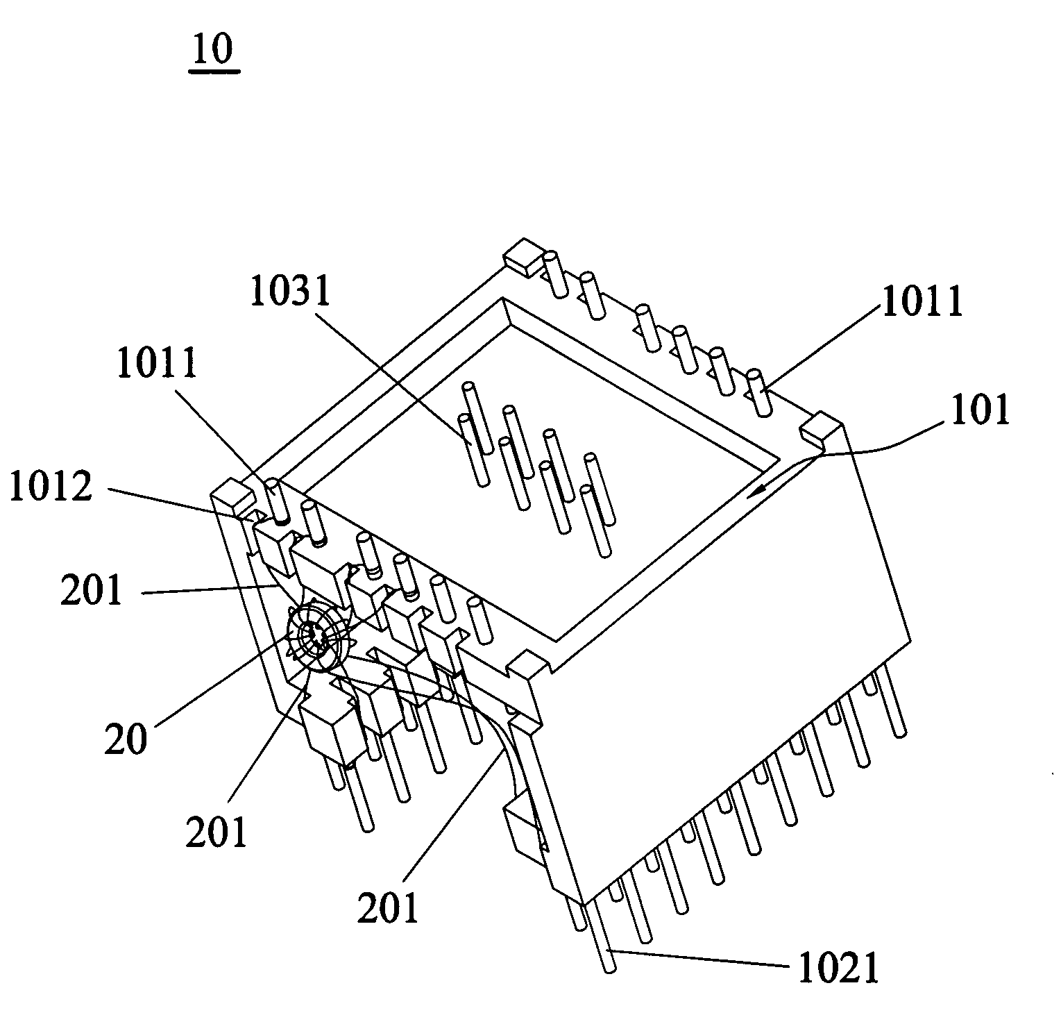
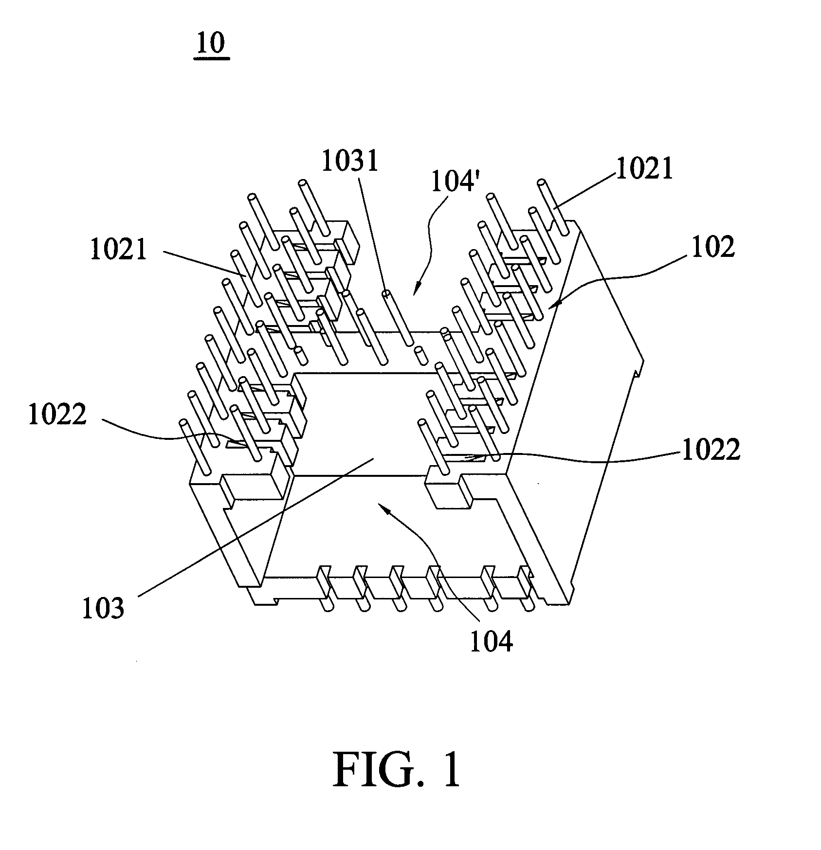
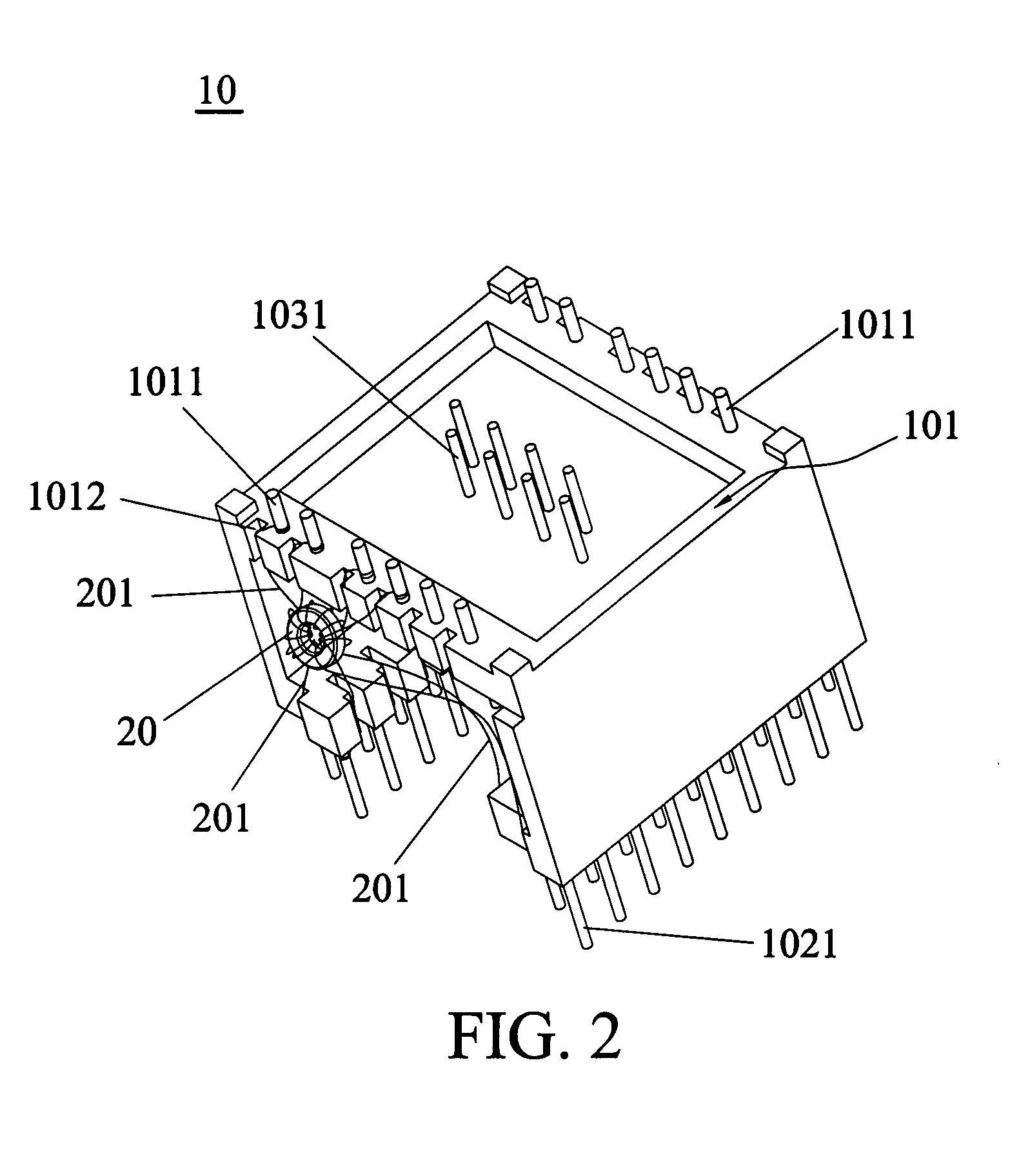
[0025]Referring to FIGS. 1 and 2, the coil connecting frame 10 includes a first surface 101 and a second surface 102. The first surface 101 is opposite to the second surface 102. The first surface 101 includes a plurality of first pins 1011 disposed thereon. The second surface 102 includes a plurality of second pins 1021 disposed thereon. The coil connecting frame 10 further includes an electrically connecting portion 103 disposed between the first surface 101 and the second surface 102 to divide the coil connecting frame 10 into two sections 104 and 104′. The electrically connecting portion 103 includes a plurality of conducting pins 1031 penetrating through both the ...


PUM

PropertyMeasurementUnit
magneticaaaaaaaaaa
densityaaaaaaaaaa
sizeaaaaaaaaaa

Abstract

A filter mainly includes a coil connecting frame, a plurality of coils received in the frame, and a first circuit board. The frame comprises a first surface with a plurality of first pins and a second surface, opposite to the first surface, with a plurality of second pins. The first pins are connected to the first circuit board, and the second pins are connected to an external electronic device while both the first and second pins are connected to the coils. The coil connecting frame further includes an electrical connecting portion between the first surface and the second surface with a plurality of conducting pins which penetrate through the first and second surfaces to connect to the circuit board and the second pins or external electronic device.

Description

[0001]This Non-provisional application claims priority under U.S.C.§ 119(a) on Patent Application No(s). 095105316, filed in Taiwan, Republic of China on Feb. 17, 2006, the entire contents of which are hereby incorporated by reference.BACKGROUND OF THE INVENTION[0002]1. Field of the Invention[0003]The invention relates to a filter and a coil connecting frame thereof, and in particular to a modulized filter and a coil connecting frame thereof.[0004]2. Description of the Related Art[0005]In order to manufacture electronic devices precisely, a surface mount device (SMD) is typically used in printed circuit boards to join electronic elements thereon. Conventionally, there are two methods of manufacturing magnetic elements described in the following.[0006]One method of manufacturing conventional magnetic elements is winding a copper line on an iron core to form a coil, and one end of the coil is fixed on a pad of the printed circuit board by soldering. Also, a surface mount device (SMD) ...

Claims


Application Information

Patent Timeline
Patent Type & Authority Applications(United States)
IPC IPC(8): H01F27/30
CPCH01F17/062H01F27/022H01F27/027H01F27/29H01R13/6658H05K2201/10606H05K1/145H05K3/301H05K3/3447H05K2201/10424H01R13/719
Inventor WANG, JUNLI, XIN-HUAHSU, HAN-CHENG
Owner DELTA ELECTRONICS INC
Why Eureka
Try Eureka