
Wideband active phased array antenna system

a phased array, wideband technology, applied in antennas, radio transmission, electrical equipment, etc., can solve the problems of beam pointing errors or beam squint, not true for wideband applications, and often precludes the use of practicable considerations

Active Publication Date: 2007-08-23
NORTHROP GRUMMAN SYST CORP
View PDF14 Cites 47 Cited by
  • Summary
  • Abstract
  • Description
  • Claims
  • Application Information

AI Technical Summary

Benefits of technology

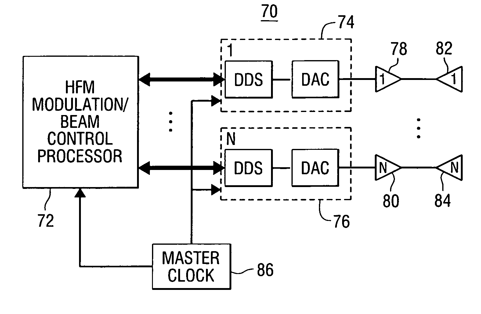
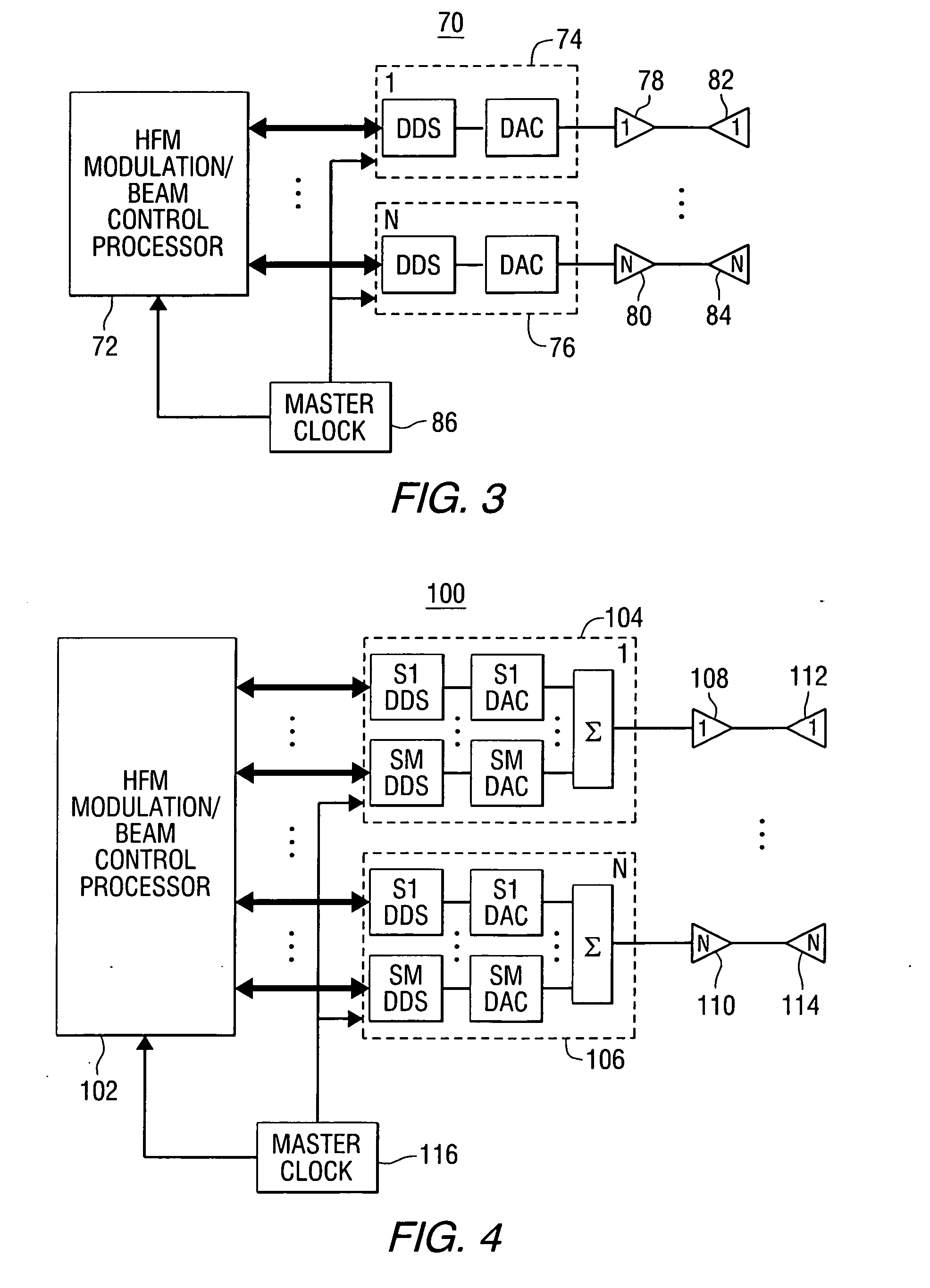
[0011] This invention provides a transmission system comprising a plurality of antenna elements; a plurality of power amplifiers, each of the power amplifiers being connected to one of the antenna elements; a plurality of waveform/beam synthesizer assemblies, each of the waveform/beam synthesizer assemblies being connected to one of the power amplifiers; a processor for controlling modulation and beam forming/steering functions of the waveform/beam synthesizer assemblies; and a master clock for synchronizing operation of the processor and waveform/beam synthesizer assemblies; wherein each of the waveform/beam synthesizer assemblies generates a transmit element signal with embedded pha

Problems solved by technology

A direct method of signal alignment would be to use time delay devices, but practical considerations often preclude their use.
Although the frequency dependence can usually be ignored for narrowband applications, this is not true for wideband applications.
Failure to compensate for the frequency dependence results in beam pointing errors or beam squint.
Certain architectural implementations of phased array systems inherently possess critical disadvantages such as limited bandwidth, limited accuracy in shaping or pointing the beam, and reduction of effective isotropic radiated power (EIRP) due to inefficient multiple beam generation techniques.
In practice, the wideband limit of any particular architecture is driven by the amount of beam squint that is acceptable for a given application.
This could lead to an amplifier damage condition.
In summary, the use of a constant phase in a phase based steering approach is inadequate to steer a wideband signal.

Method used


Image

  • Wideband active phased array antenna system
  • Wideband active phased array antenna system
  • Wideband active phased array antenna system

Examples


Embodiment Construction

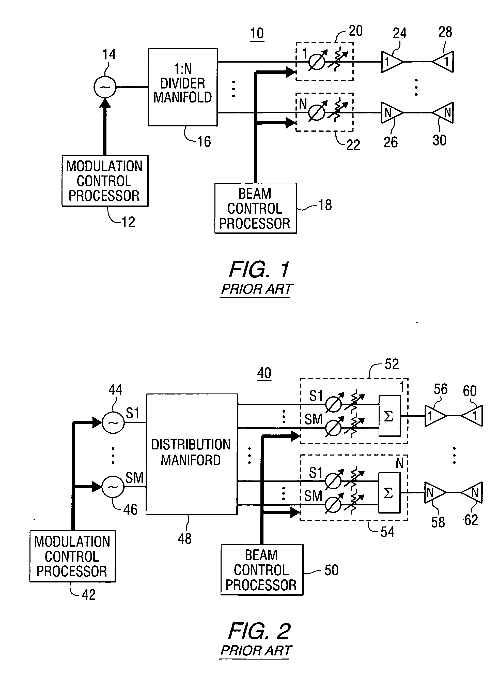
[0017] Referring to the drawings, as a point of reference, prior art active phased array systems are illustrated in FIGS. 1 and 2. FIG. 1 illustrates an active phased array system 10 for single signal transmission including a modulation control processor 12, a signal generator 14, a manifold 16, a beam control processor 18, a plurality of time delay devices / attenuators 20 and 22, a plurality of power amplifiers 24 and 26, and a plurality of antenna radiating elements 28 and 30.

[0018]FIG. 2 illustrates an active phased array system 40 for simultaneous signal transmission including a modulation control processor 42, a plurality of signal generators 44 and 46, a manifold 48, a beam control processor 50, a plurality of time delay devices / attenuators / summer assemblies 52 and 54, a plurality of power amplifiers 56 and 58, and a plurality of antenna radiating elements 60 and 62.

[0019] For the architectures of FIGS. 1 and 2 to meet the requirement for wideband operation, time delay device...


PUM


Abstract

A transmission system comprises a plurality of antenna elements; a plurality of power amplifiers, each of power amplifiers being connected to one of the antenna elements; a plurality of waveform / beam synthesizer assemblies, each of the waveform / beam synthesizer assemblies being connected to one of the power amplifiers; a processor for controlling modulation and beam forming / steering functions of the waveform / beam synthesizer assemblies; and a master clock for synchronizing operation of the processor and waveform / beam synthesizer assemblies, wherein each of the waveform / beam synthesizer assemblies generates a transmit element signal with embedded phase offset and amplitude adjustments in response to control signals from the processor, and each of the plurality of antenna elements radiates one of the transmit element signals. A method of producing one or more beams using an array of antenna elements is also provided.

Description

FIELD OF THE INVENTION [0001] This invention relates to radio frequency (RF) transmission systems, and more particularly to such systems that include phased array antennas. BACKGROUND OF THE INVENTION [0002] Phased array antenna systems can provide rapid beam steering, the ability to generate simultaneous beams, dynamic adjustment of the characteristics of the beam pattern, and graceful degradation. [0003] The underlying principle for beam steering in phased arrays is the alignment of the elemental signals in space such that they add constructively in a desired direction. A direct method of signal alignment would be to use time delay devices, but practical considerations often preclude their use. An often-used alternative is phase based beam steering, in which the elemental signals are appropriately phase shifted. Effectively, a phase gradient (or taper) is applied across the elements. For a given pointing angle, the value of the gradient depends on the signal frequency. Although th...

Claims


Application Information

Patent Timeline
IPC IPC(8): H01Q3/00
CPCH01Q21/0006H04B7/0617H01Q21/20
Inventor DULMOVITS, JOHN MICHAEL JR.BAJIT, RONALD JOSEPH
Owner NORTHROP GRUMMAN SYST CORP
Learn More