
Control System

Inactive Publication Date: 2007-08-23
HONDA MOTOR CO LTD
View PDF4 Cites 16 Cited by
  • Summary
  • Abstract
  • Description
  • Claims
  • Application Information

AI Technical Summary

Benefits of technology

[0011] With the configuration of this control system, a target value as a target of the output of a controlled object is calculated according to the state of the controlled object; one filtering target value for setting follow-up responsiveness of the output of the controlled object to the target value is calculated by performing a predetermined filtering process on the calculated target value; and a plurality of control inputs are calculated with a plurality of predetermined feedback control algorithms, respectively, in a manner such that the output of the controlled object converges to the calculated one filtering target value. The control inputs are thus calculated with target value filter-type two-degree-of-freedom sliding mode control algorithms, and therefore it is possible to configure the predetermined filtering process and the predetermined feedback control processes, independently of each other, whereby it is possible to set the follow-up responsiveness of the output of the controlled object to the target value, and the converging behavior of the difference between the target value and the output of the controlled object, caused by disturbance or the like, separately from each other. More specifically, by properly configuring the predetermined filtering process to be performed on the target value, it is possible to ensure excellent follow-up responsiveness of the output of the controlled object to the target value, and at the same time, by properly configuring the predetermined feedback control processes, it is possible to cause the output of the controlled object to converge to the target value without causing any overshooting or oscillating behavior, to thereby stabilize the converging behavior of the output of the controlled object to the target value. Moreover, since the control inputs are calculated by sharing one filtering target value, it is possible to avoid the feedback control processes using the respective control inputs from interfering with each other. As is apparent from the above description, the control system is capable of improving both the stability and the accuracy of the control.
[0029] With the configuration of this preferred embodiment, the two control inputs for controlling the boost pressure and the EGR amount of the internal combustion engine, respectively, make it possible to perform feedback control of the intake air amount of the engine without causing overshooting or the like, such that the intake air amount properly converges to a target value thereof, and at the same time avoid boost pressure control and EGR control from interfering with each other. As a result, it is possible to enhance the stability and the accuracy of the intake air amount control of the engine.

Problems solved by technology

According to the above described conventional control system, although the engine speed is feedback-controlled through two control processes by the two control inputs, there is a fear that the two control processes interfere with each other, since the characteristics of the control processes are different from each other.
More specifically, when the ignition timing is controlled, response delay and dead time of the control are short, and hence it is possible to cause the engine speed to quickly converge to the target engine speed.
For example, in cases where the target engine speed is temporarily and sharply increased e.g. by racing by a driver during idling, if the ignition timing is controlled in a manner coping with the increase in the target engine speed, the retard amount of ignition timing becomes too large, which can result in reduction of combustion efficiency.
However, the engine speed cannot be controlled by the control process as finely as by the ignition timing control process, which results in degraded control accuracy.
Moreover, response delay and dead time are larger in the feedback control process of the intake air amount than in the feedback control process of the ignition timing.
This results in the degraded convergence of the engine speed to the target engine speed.
As to the conventional control system, there is a fear that the two control processes interfere with each other due to the above-described differences in characteristics therebetween, causing reduction of both the stability and the accuracy of the control.
Furthermore, in the general feedback control methods, such as PI control, when a sudden change in the target engine speed as mentioned above has occurred, the engine speed control tends to cause overshooting or undershooting of the target engine speed and an oscillating behavior of the controlled engine speed, and attempts to avoid these inconveniences cause reduction of the convergence rate of the engine speed to the target engine speed.
In short, it is difficult to positively maintain both the converging behavior and convergence rate of the engine speed to the target engine speed in excellent conditions, which results in further degradation of both the stability and the accuracy of the control.

Method used


Image

  • Control System
  • Control System
  • Control System

Examples


Embodiment Construction

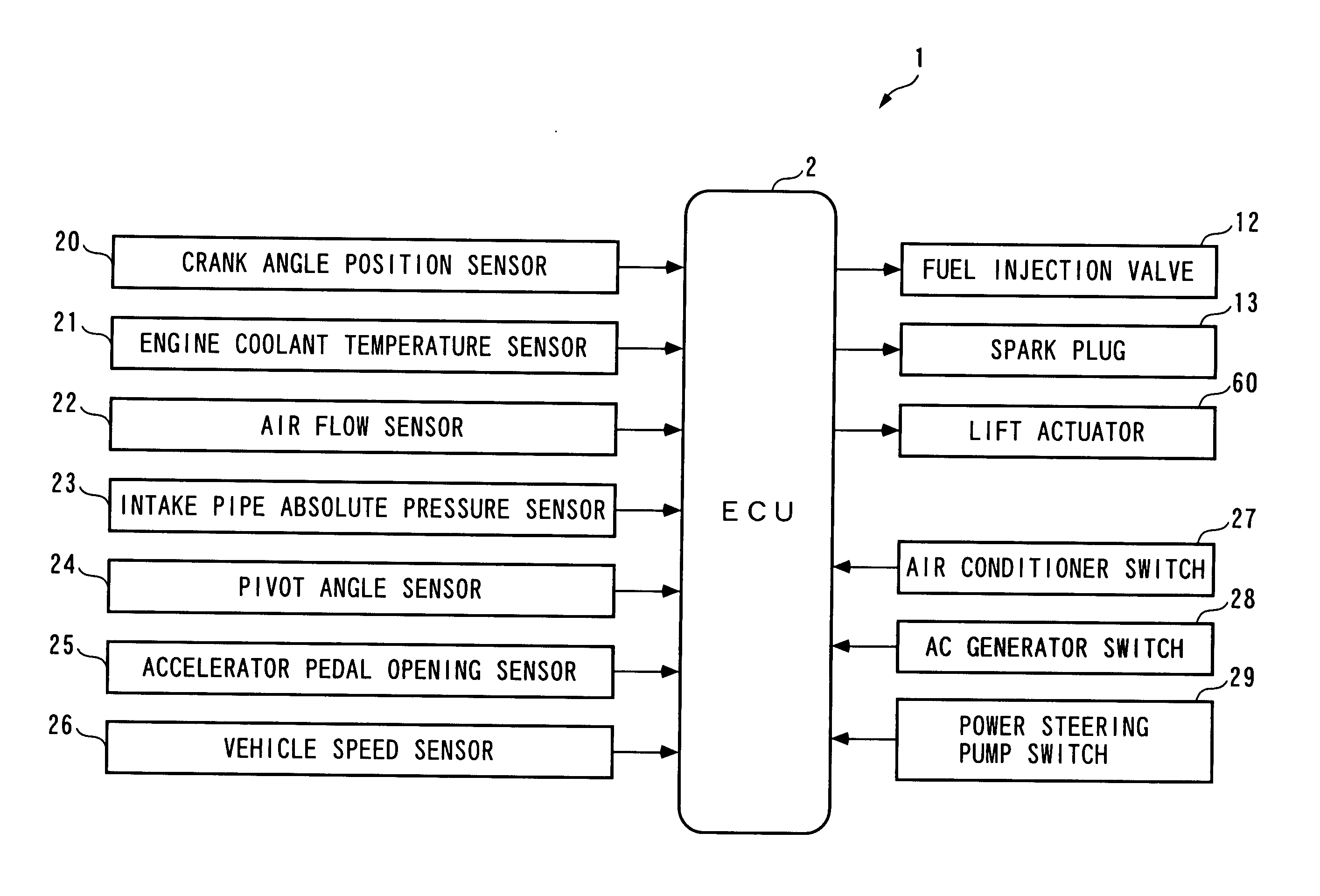
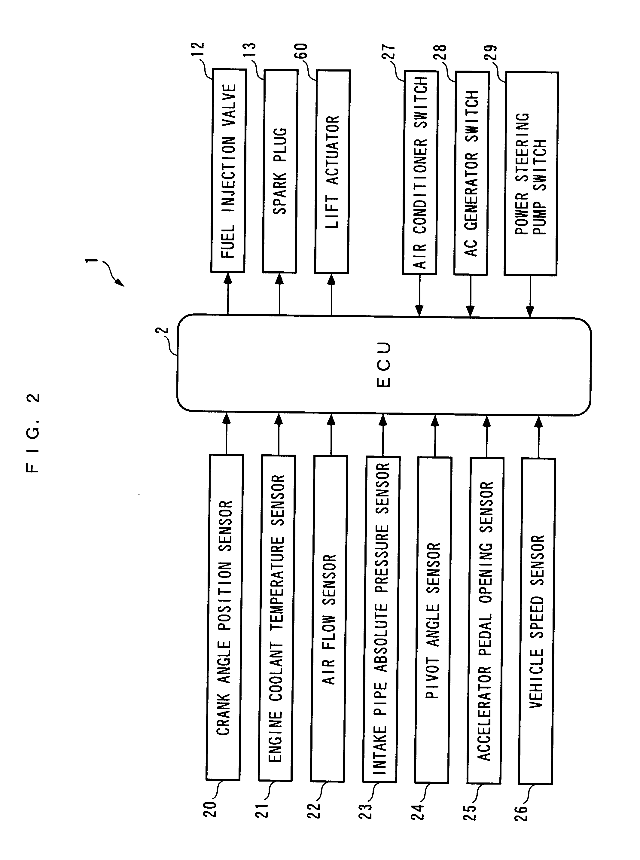
[0070] Hereafter, a control system according a first embodiment of the present invention will be described with reference to drawings. The control system 1 includes an ECU 2, as shown in FIG. 2. As described hereinafter, the ECU 2 carries out control processes, including an idle engine speed control process, depending on operating conditions of an internal combustion engine (hereinafter simply referred to as 22“the engine”) 3.

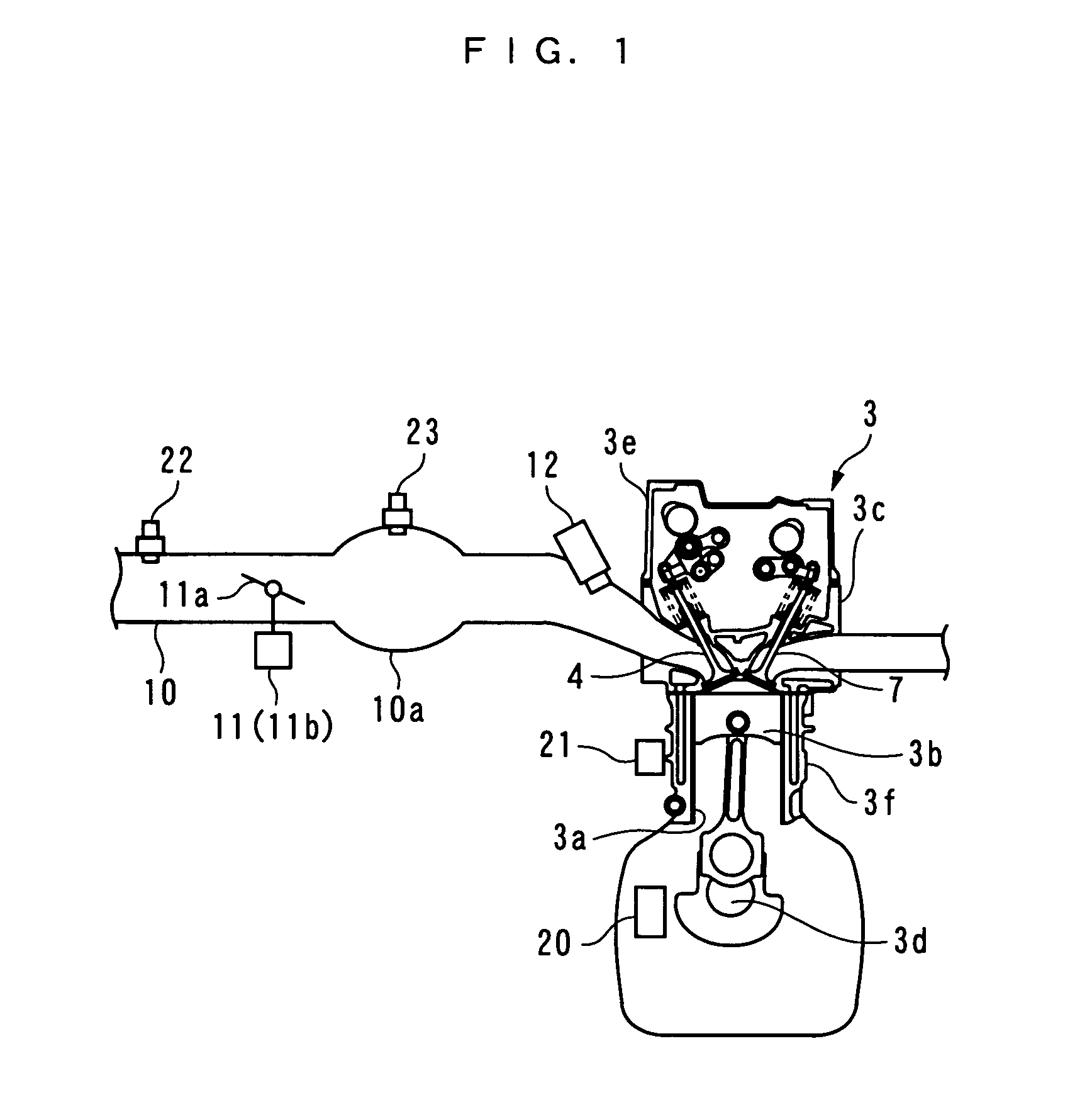
[0071] Referring to FIGS. 1 and 3, the engine 3 is an in-line multicylinder gasoline engine having a multiplicity of pairs of cylinders 3a and pistons 3b (only one pair of which is shown), and installed on a vehicle, not shown. The engine 3 includes an intake valve 4 and an exhaust valve 7 provided for each cylinder 3a, for opening and closing an intake port and an exhaust port thereof, respectively, an intake camshaft 5 and intake cams 6 that actuate the intake valves 4, a variable intake valve-actuating mechanism 40 that actuates the intake valves 4 to open ...


PUM


Abstract

A control system which is capable of enhancing both the stability and the accuracy of control when the output of a controlled object is feedback-controlled by a plurality of control inputs. An ECU 2 of a control system 1 controls engine speed NE during idling by an ignition control input Usl_ig and an intake control input Usl_ar. The ECU 2 calculates a target engine speed NE_cmd according to an engine coolant temperature TW and the like (step 3), and determines the ignition control input Usl_ig and the intake control input Usl_ar with a plurality of predetermined target value filter-type two-degree-of-freedom sliding mode control algorithms [equations (1) to (12)] sharing one switching function σne therebetween, such that the engine speed NE converges to the target engine speed NE_cmd (steps 4 to 7 and 9).

Description

FIELD OF THE INVENTION [0001] This invention relates to a control system that feedback-controls the output of a controlled object by a plurality of control inputs. BACKGROUND ART [0002] Conventionally, a control system that feedback-controls an engine speed during idling of an internal combustion engine has been proposed in Patent Literature 1. This engine includes a bypass passage that bypasses a throttle valve, an idling adjusting valve for opening and closing the bypass passage, an ignition coil, and so forth. As described hereinafter, the control system controls both the intake air amount and the ignition timing during idling of the engine such that the engine speed converges to a target engine speed. [0003] More specifically, first, during idling, the target engine speed, a basic intake air amount, and a basic ignition timing are set according to operating conditions of the engine. Next, the difference between an actual engine speed and the target engine speed is calculated, an...

Claims


Application Information

Patent Timeline
IPC IPC(8): G06F17/00F01L1/34F02B75/02F02B37/00F02B37/18F02D13/02F02D21/08F02D23/00F02D31/00F02D37/02F02D41/08F02D41/16F02D43/00F02D45/00F02M25/07F02P5/15G05B11/32G05B11/36G05B13/02
CPCF02D21/08F02D23/00F02D31/003F02D37/02F02D41/1403Y02T10/144F02M25/0707F02P5/1508G05B11/32Y02T10/46F02D2041/001F02M26/05Y02T10/12Y02T10/40
Inventor YASUI, YUJITAGAMI, HIROSHISAITO, MITSUNOBUHIGASHITANI, KOSUKESATO, MASAHIRO
Owner HONDA MOTOR CO LTD
Learn More